I’ve been trying to get reliable data from my Solax Installation for a couple of months now and I’ve tried all manner of methods, some vaguely work but they show ‘unavailable’ for the most part and maybe give me a reading every couple of minutes if I am lucky.
I found your custom component today and I’ve got it installed but no matter what I try every single entity is unavailable.
My inverter is connected up via Pocket LAN (pictured above), I know the IP, though I am not sure which model it is - though I’ve tried both with and without boxes ticked. It was installed in January and I vaguely remember something about a Gen 4, but I do not know where I found this and I don’t seem to be able to find it again.
Are there any starters for 10 about where I should be looking or anything else the I need to do to be able to get the data from the inverter. I’d really like to be able to do it without the cloud as it’s not really real-time with the 5 minute intervals and it just doesn’t display well in Home Assistant - showing was unavailable for the most part. I’ve added a photo of the inverter if it helps.
I’d really like to be able to get all of this information in one place and maybe link it to automations if possible - so that I can any excess energy generated where possible as I have an air source heat pump for my central heating and I wouldn’t mind using the solar energy to power it where possible.
Thanks, do you have a link to an example of the ethernet adapter and which port it plugs into? I’m running HA on a Mac mini through VirtualBox. Will using this disconnect it from the cloud?
It looks like the cheaper versions ie USR-TCP232-304 only convert it to a Virtual Com Port, so I don’t know how easy that would be to pass into your VM?
@Voreland are you able to share what Model RS485 - Ethernet adaptor you are using?
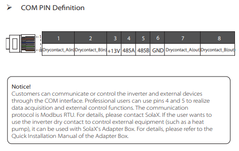
Just had a look in the Manual for Gen4, looks like this port. You will need to connect Pins 4 - 6 to your adaptor.
If you want to remove it from the Cloud remove your Pocket Lan.
I’m getting the impression that we’re at about the limit of what I can do. I’ve not no idea how I would connect pins 4-6 to anything. There are no cables coming out of that port on the Inverter and the port is covered over. I don’t think that I could connect anything else to my Virtual Machine as it is at the other end of the house and down a floor. The best bet for that would be ethernet, but £43 for a bit of kit that I don’t think I can set up might be pushing it a bit too far for my partner…she’s very accommodating but…
I really don’t understand why they don’t allow the Pocket LAN to work locally.
Past couple of releases for those who don’t follow the GitHub page: (0.4.10 removes the need to connect the Inverter to the Cloud at all! You can now unlock Inverter control from the Integration)
“The discharge time allows you to use the battery only from the start time to the end time”
While the sensors read on Gen3 and you can alter the times I can’t verify if it does anything on the Gen3. Might only apply to Gen2 (Does not force Discharge into the Grid)
Gen2
Removed the following sensors as they don’t exist on Gen2
Hi,
Sorry I was away. It gave me a bit more idea, but it’s still not something that I know how to do. I also haven’t been able to find a converter at anything close to a price that I can justify.
Hi, I’ve used Wills cloud interface package for a while to monitor but i’m wanting to be able to control the inverter so I’m trying to get this working and having problems getting it to display anything. I was getting rejected connection errors and decode errors in my logs so made some tweaks to the vircom config (added my HA IP address to the Multi Dest IP and Port list and changed the transfer protocol), i can now see RX and TX packets showing in vircom and I get no log errors in HA, but still not data! Here is my Vircom settings, can you see anything wrong?
I then rebooted to be sure, and everything is showing up as ‘unknown’
I suspect i have the modbus set up wrong but i’m a complete novice to know where to go next!
another thought, I connected the blue and blue and white wires are directed, but noticed above Will suggested connecting the GRND too, would this be affecting it?
any pointers please, i’m good at following instruction but don’t have an understanding of system to be able to sus myself.
Have you tried swapping the Blue and Blue-white wire around? (Or did you follow the Wiki?)
GND / Ground wire is more for longer wire runs. I don’t know exactly when you need to connect GND but I know RS485 can run upto 1200M. If you do need GND it’s pin 6 according to the image I posted a couple of pics up.
Might need input from @infradom or @Voreland as I personally haven’t used an RS485 - Ethernet Adaptor as my Gen3 has built in Ethernet port which supports Modbus over TCP
Hi Will,
Thanks for you and all’s work on this, I’m looking forward to getting it working.
I used the wiki but will swap over just in case. It’s only a 1.8m cable but I can connect the ground if it would help.
I’ll have a look in the morning and see if either makes a difference
If you followed the Wiki I would say it’s a software setting then.
We can get some extra screen shots on the Wiki. I also plan to add a page of known working RS485 to X adaptors. As I am guessing not all will be created equally or some might only function as perhaps a slave device etc.
I did not connect ground. That should not be needed, just the 2 wires
I see in your vircom config that you have selected REALCOM
In my config, I have selected Modbus_TCP Protocol as transfer protocol