Maybe worth checking
Frenck’s Doorbell
He used GPIO2 for an addition button on a standard ESPHome relay

Maybe worth checking
Frenck’s Doorbell
He used GPIO2 for an addition button on a standard ESPHome relay
Will try after work and follow up, thx.
On first look, it seems to me that Frenck’s Doorbell example will hold circuit closed only until taster button is pressed and that circuit will open again right after button is released, maybe I’m wrong? I would need to shorten some PINs and to switch relay to another position permanently. And with next button press to switch relay to first position permanently, etc. if this is possible at all.
You just need to toggle the relay pin. Completely possible.
EDIT: Oh, do you mean on some of PINs where relay it self is soldered on board? It would be appreciated if you could tell me which one, I’m not sure can I broke something if try one by one  thx
thx
Sorry for stupid question , but what PIN is it?
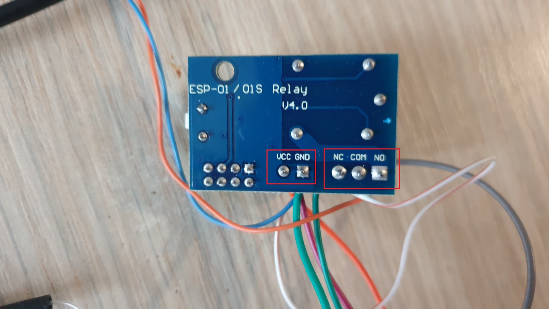
* There are input PINs from the bottom, VCC and GND, these are for supplying relay board with power
* There are output PINs from the bottom, NO, COM and NC, these are for final device (normally open, common and normally closed)
* Or do you mean on some of PINs in yellow 8 PIN header?
You are too focused on hardware.
As I said before, you need to configure the ESP to do what you want.
Since you seem adamant on tasmota, then this is as far as I can help you.
I know there are people that is good at tasmota and they can probably do the syntaxes to configure, but that is out of my reach.
You need to do like the guide linked above bend out a pin to hook up the button to, and then it’s completely black for me with tasmota.
In ESP-Home, you would set up that pin as an sensor and on trigger switch the state of the output pin controlling the relay.
Ah, understand now that I misunderstood you in your previous post, sorry for that.
Seems to be some issues with these boards.
I already read regarding removing R2 resistor and solder CH_PD to 3.3V, and already read that topic as well. I think my case isn’t related with that, cause all of them had problems with booting if I remember good. I have no problems with software booting and operating at all - everything is working as expected. I just don’t know how to mount physical toggle button
Ok, so, if this could be helpful…
Actually, my mistake was misunderstood of taster button I bought on Aliexpress 
Talking about these buttons, momentary self-reset, 12mm: 12/16/19/22mm Waterproof Metal Push Button Switch LED Light Momentary Latching Car Engine Power Switch 5V 12V 24V 220V Red Blue|Switches| - AliExpress
These of 12mm (I bought) are having 4 PINs, one marked with +, another one marked with - and 2x unmarked PINs. My mistake was that I meant + and - are PINs which opening/closing circuit  .
.
Of course most of you probably knows these PINs are for power supplying built-in LED and unmarked PINs are actually Normally Open and Common. So everything is working as it should work with Tasmota now. I soldered NO and COM button PINs to GPIO2 and GND on module and assigned “Button” function to GPIO2 inside Tasmota.
Not integrated to HA yet, cause I firstly want to make wooden case and mount it on lamp, but integration to HA will be easy part.
Final product - pure DIY:
Please ignore my double taps, it is little hard for me to record and clicking another screen same time
In summary ~$4
Not really related with topic, but my wooden lamp got an upgrade to v2.0
Basic one color white LED strip had been changed with WS2812B, relay removed and Tasmota replaced with ESPHome:
hello
i know is late after last reply of this topic but i need to integrate this in HA .
i have tried this code
captive_portal:

switch:
  - platform: gpio
    pin: 0
    id: relay
    name: "apasaL"
    inverted: true
    on_turn_on:
    - delay: 500ms
    - switch.turn_off: relay

binary_sensor:
  - platform: gpio
    pin: 2
    name: "btn"
    on_press:
      then:
        - switch.turn_on: relay
but the button does not work , instead gpio 2 acts like a touch button , when i touch gpio 2 with my finger it do the job but when shorted to ground is not.
please help ne with the code
thanks in advance
Never being late
Few questions:
on_turn_on automation. I think that you copy/pasted example from here, but it is just an example)It would be good to explain in more details what you are trying to achieve (and which board/microcontroller you are using). If you are trying (but only if my prophecy is on right track  ) to make a simple switch, which you will be able to control from both sides - from HA and with physical button switch, on ESP01s, then try this:
esphome:
  name: <your-name-here>

esp8266:
  board: esp01_1m

logger:

api:

ota:

wifi:
  ssid: !secret wifi_ssid
  password: !secret wifi_password

captive_portal:

switch:
  - platform: gpio
    pin: 0
    id: relay
    name: "<Your Name Here>"
	inverted: true

binary_sensor:
  - platform: gpio
    pin:
      number: GPIO2
      mode: INPUT_PULLUP
      inverted: True
    name: "<Your Another Name Here>"
    on_click:
      then:
        - switch.toggle: relay
(Sorry, I didn’t tested code above, cause currently I have only one ESP01s ESPHome “switchable” device, which is running muuuuch more complex code, and which btw have no switch component at all but light instead, but I reduced that complex code to minimum and believe above example should work)
hello , yes you are right , is about esp 01 and i need to add a momentary button like a doorbell , i a new to this and testing and trying to understand how it works.
now i got tested the toggle function and it seems that i can get rid of the delay .
thanks for quick reply , i will test the code and see what happens.
just got it !!!
captive_portal:

binary_sensor:
- platform: gpio
  pin:
    number: GPIO2
    mode: INPUT_PULLUP
    inverted: True
  name: "btn"
  on_press:
    - delay: 500ms
    - switch.toggle: relay_1


switch:
- platform: gpio
  name: "apasaL"
  pin: GPIO0
  id: relay_1
  inverted: True
  on_turn_on:
    - delay: 500ms
    - switch.turn_off: relay_1
this code works for me to have a momentary button (like a doorbell) that is integrated in HA and is also triggered when is pressed the button on gpio 2
Processing: 20230124_195027.mp4…

Cool. I am glad you accomplished your goal!
thanks for helping me .
now i am trying to get it to be a switch
again thanks for quick response
have a nice evening
Great tips. Helped to reach my target.
captive_portal:

binary_sensor:
- platform: gpio
  pin:
    number: GPIO2
    mode: INPUT_PULLUP
    inverted: True
  name: "btn"
  on_press:
    - delay: 500ms
    - switch.toggle: relay_1
  on_release:
    - delay: 500ms
    - switch.toggle: relay_1


switch:
- platform: gpio
  name: "apasaL"
  pin: GPIO0
  id: relay_1
  inverted: True

Nice , that you have get it to work .