I desolder the metal outside part of a standard USB male breakout board, pull the contacts out and secure the metal part to my workbench. Put in a flathead screwdriver and push the plastic part out, sand it down so it fits the AC USB port and reassemble the connector.
Ok I have a Dremel so that shouldn’t be too hard. I just noticed that it seems only the mini-split has the weird USB port. My 2 window air conditioners have a regular USB-A female so at least I’ll only need to do this for one of them.
One more question. Any reason I can’t use these?
I’m lazy and I pass by a Microcenter every day.
As long as they accecpt the esphome programming and have tx/rx, i don’t think it will be an issue…esp=esp 
Hi! I was working on my version of the component and found that the climate control works much better with a separate temperature sensor. Are there any plans to add a CustomAPIDevice for a separate temperature (and humidity) sensor?
1 Like
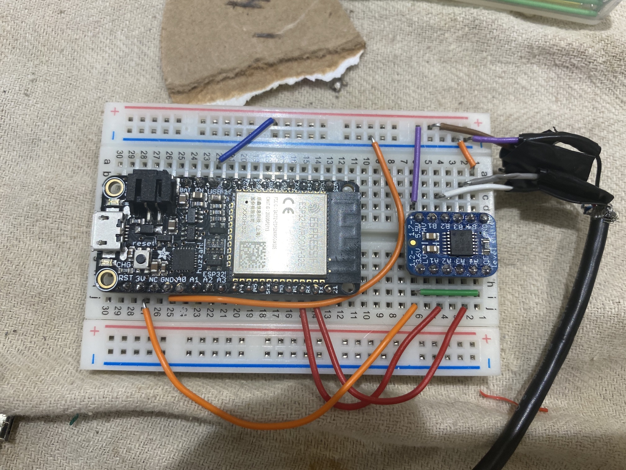
Ok I’m having some trouble here. I’m using an Adafruit ESP32 with an Adafruit TXB0104 level shifter.
This is all I’m getting.

I have
 # UART settings for Midea dongle (required)
 uart:
   tx_pin: GPIO17
   rx_pin: GPIO16
   baud_rate: 9600
in the YAML file. At first I had mistakenly used pins 1 and 3 which was in the example code which according to this is incorrect and that it should be 16 and 17. Still getting nothing. Also tried using some of the other GPIO pins, same deal.
I’m not sure if I have a configuration issue or a hardware one. I tried more than one level shifter, and I’m getting 5V on the HV side and approx 3.3v on the LV side. Sometimes the TX pin coming from the A/C is low (like 2v) but I’m guessing that’s normal when checking a UART pin with a multimeter?
I also tried putting the Midea dongle back in to make sure it wasn’t an issue with the a/c itself but it seems to be fine, and I also tried more than one A/C (I have 3). Not sure what’s going on here and I’m hoping someone might have some insight.
As suggested in the Telegram group, change RX and TX (physically). That should solve the problem. 
If not, please report back.
I think I forgot to mention, but yes I’ve tried it both ways.
I had the same issue and swopping resolved it. After the tx query you should get an rx frame. Check all connections. I had a bad crimp. Check continuity on all cables to the AC?
Please show a picture of your connection to the A/C (to see the cable colors and how/where the are connected). Like the other end of the cable from the pic above.
EDIT: and the complete yaml from ESPHome.
The other end is just a USB cable (it’s one of the window units that uses a regular USB female) but I removed the electrical tape so you can see which wire is soldered to what.

The YAML file is here:
esphome:
  name: mideatest1
  platform: ESP32
  board: featheresp32

wifi:
  ssid: "NERV24"
  password: "[redacted]"

  # Enable fallback hotspot (captive portal) in case wifi connection fails
  ap:
    ssid: "Mideatest1 Fallback Hotspot"
    password: "DLlwng3yji0R"

captive_portal:


# Enable Home Assistant API
api:

ota:

# Example configuration entry

# Disable logging over UART (required)
logger:


# UART settings for Midea dongle (required)
uart:
  tx_pin: GPIO17
  rx_pin: GPIO16
  baud_rate: 9600

# Optional (if you want modify settings)
midea_dongle:
  strength_icon: true

# Main settings
climate:
  - platform: midea_ac
    name: "My Midea AC"
    visual:
      min_temperature: 18 °C
      max_temperature: 25 °C
      temperature_step: 0.1 °C
    beeper: false
    swing_horizontal: true
    swing_both: true
    outdoor_temperature:
      name: "Temp"
    power_usage:
      name: "Power"
    humidity_setpoint:
      name: "Hum"
You have to disable the logger component:
logger:
  baud_rate: 0
Ok just tried that. Same thing. 
The logger baud rate set to zero is necessary, so leave it in.
Now change TX/RX
I know, tedious, but with the logger enabled it can’t work, so we have to disable the logger and start again with all the other possible things.
When you changed that, what is the output in ESPHome (the pic you already took)?
EDIT: Wait, are you sure, that is a feather board? It looks way more like a NodeMCU…
Ok tried switching TX/RX again. Same thing. The output in ESPhome is the same as the pic I took earlier.
Just out of curiosity, would connecting TX/RX of the ESP32 together (doing this on the bench, disconnected from the A/C entirely) be a valid loopback test? Because I just tried it and I’m seeing this sporadically:
[13:41:41][D][midea_dongle:094]: TX: AA 22 AC 00 00 00 00 00 03 03 41 00 00 FF 00 00 00 00 00 00 00 00 00 00 00 00 00 00 00 00 00 00 00 84 68
[13:41:42][D][midea_dongle:029]: RX: AA 20 02 05 45 44 68 69 41 49 A8 04 44 2B B3 BE 81 A1 52 45 95 35 B3 0A 91 98 52 35 49 4B 0B 60 91
[13:41:42][W][midea_dongle:031]: RX: frame check failed!
Even though it’s not repeating back every single TX string can I at least assume the ESP32 as it’s configured is capable of receiving?
Ok loopback test is working fine. Verified that TX/RX pins on the Feather map to GPIO16 and 17. I also ran the loopback through level shifter and it’s working fine there too. Not sure what the problem is at this point. I ordered an oscilloscope from Amazon and it should be here tomorrow.
Ok it works! Turns out the issue was the Adafruit TXB0104 based level shifter I was using. Either they were defective (I tried two!) or they don’t work for this application for reasons I don’t understand yet. I actually needed to buy an oscilloscope to figure this out. Fortunately I was able to pick up a Sparkfun converter at Microcenter and it works like a charm. So just some caution for anyone who used the Adafruit converter and ends up having the same problem.
2 Likes
If your time permits, you could ask Adafruit for a statement? It would be interesting to know why this level shifter isn’t working as expected.
But it’s nice to see, how you figured it out (I followed your experiments on Telegram). 
The display is extremely bright and annoying, so we still need the remote on our nightstand to turn it off. Or we have to disable the display more permanently ![]()
Would it be possible to use the ESP to send the IR code to disable the display, by connecting an IR LED to it and point towards the IR receiver internally? Did anyone manage to decipher the IR data yet?
So far it seems the display dimmer is IR only and not t controllable over uart.
Some people have started developing it, but not sure what the status is…