@infradom in case you don’t get GitHub notifications I have started a discussion on your proposed changes.
Sorry for late reply @wills106, I have my connection from the built in modbus to a modbus/ethernet converter. I’ve set up the connection according to the document from a gen3 and it seems to be responding correctly.
Version 0.4.0
ATTENTION: Gen 4 is Work in progress - only tested for X3, Gen4 X1 not tested - Use at your own risk !!!
- Great thanks to @infradom for help adding in Serial Modbus and the Gen 4
- Add support for X3 Gen4 (X1 Gen4 should work also, but completely untested)
- Add support for serial Modbus RTU connection (needed as the Gen4 modbus is not accessible over TCPIP) I am using a low-cost 2€ usb-to-RS485 adapter. By default Gen4 device is set to 19200 baud.

- If you are trying this on a non Hybrid (X1 Air, X1 Mini, X1 Boost) start off without setting any of the tick boxes and see what values you have.

Version 0.4.1
- number.solax_battery_minimum_capacity now survives restart of HA
Version 0.4.2
Fixed the following: Gen2 X1
- sensor.solax_battery_charge_float_voltage
- sensor.solax_battery_discharge_cut_off_voltage
- sensor.solax_export_control_user_limit
Gen2 & Gen3
- select.solax_run_mode_select now select.solax_charger_use_mode
- select.solax_grid_charge_select now select.solax_allow_grid_charge
Changed response from sensor.solax_allow_grid_charge
- “Forbidden”
- “Charger Time 1”
- “Charger Time 2”
- “Both Charger Time’s”
to
- “Both Forbidden”,
- “Period 1 Allowed”,
- “Period 2 Allowed”,
- "Both Allowed
Now matches the state of select.solax_allow_grid_charge
- select.solax_charger_use_mode & select.solax_allow_grid_charge survies a restart of HA and also responds to changes made through the SolaX Cloud portal
Set the following to be hidden as default due to them being duplicates of select / number entries
- sensor.solax_allow_grid_charge
- sensor.solax_battery_charge_max_current
- sensor.solax_battery_discharge_max_current
- sensor.solax_battery_minimum_capacity
- sensor.solax_charger_use_mode
I need a bit of help from the community.
I don’t really know which SolaX Inverters this works with in the current state. There are 4 Generations of Hybrid Inverters and numerous string only inverters as well as add on battery chargers.
I would also like to move away from having to manually select an inverter type when setting up the component, as less tech savvy users might not exactly know what inverter they have.
Ideally I would like to know the following:
Inverter Model Name
kW rating
Single / Three Phase
Single / Dual MPPT
EPS Yes Internal / Yes External / No
If Hybrid what Gen it is (less important if you don’t know)
Ideally I would also like to know the first 4 Digit’s of your serial number as I believe the above is encoded in the first 4 digits, which identify the model / type. If you don’t wish to share this publicly you can send me a PM.
You can either post here or on the Discussion Page on my GitHub
To find out your serial if you can’t see it on the Inverter casing enable sensor.solax_series_number
So for example:
SK-SU5000E
5kW
Single Phase
Dual MPPT
EPS External
Gen2
Serial: U50E
SK-TL5000E
5kW
Single Phase
Dual MPPT
EPS External
Gen2
Serial: L50E
X1-Hybrid-5.0-D-E
5kW
Single Phase
Dual MPPT
EPS External
Gen3
Serial: H1E5
X1-Hybrid-5.0-D-E
5kW
Single Phase
Dual MPPT
EPS External
Gen3
Serial: H1E5
1 Like
I have adopted proper releases now to make it work easier for future support of HACS.
You can manually add my repository into the Custom repositories section of HACS.
Once I have finished submitting a couple more PR it should be properly added into HACS.
0.4.3
Set the following to be hidden as default due to them being duplicates of number entries
- sensor.solax_export_control_user_limit
- sensor.solax_forcetime_period_1_maximum_capacity
- sensor.solax_forcetime_period_2_maximum_capacity
New README.md
Initial Support for HACS
0.4.4
Gen2 & Gen3
Padded the following with leading zeros to make them look more like real time entries:
- sensor.solax_charger_start_time_1
- sensor.solax_charger_end_time_1
- sensor.solax_charger_start_time_2
- sensor.solax_charger_end_time_2
Added the following selects:
(You need to manually add these to your Lovelace)
- select.solax_charger_start_time_1
- select.solax_charger_end_time_1
- select.solax_charger_start_time_2
- select.solax_charger_end_time_2
I have only implemented 00:00 - 06:45 so far. In 15min blocks.
Each one is hard encoded so I want to ensure these work as expect first, before doing the rest.
Once they are all finished I will set the above sensors to hidden as default.
This is a temporary stopgap till a more elegant solution can be made with encoding on the fly.
0.4.5
Gen2, Gen3 & Gen4
Added:
- Battery Awaken Button
Gen2 & Gen3
Added remaining charge times.
Now full 00:00 - 23:45 Resolution is 15mins
Gen4:
- select.solax_charger_start_time_1
- select.solax_charger_end_time_1
- select.solax_charger_start_time_2
- select.solax_charger_end_time_2
- select.solax_discharger_start_time_1
- select.solax_discharger_end_time_1
- select.solax_discharger_start_time_2
- select.solax_discharger_end_time_2
Times available 00:00 - 23:45 Resolution is 15mins
Future:
Change to a more elegant solution that can be encoded on the fly to allow greater resolution of times available.
Likely to set the following to disabled by default, due to them being duplicates of the time selects:
Gen2 & Gen3:
- sensor.solax_charger_start_time_1
- sensor.solax_charger_end_time_1
- sensor.solax_charger_start_time_2
- sensor.solax_charger_end_time_2
Gen4:
- sensor.solax_charger_start_time_1
- sensor.solax_charger_end_time_1
- sensor.solax_charger_start_time_2
- sensor.solax_charger_end_time_2
- sensor.solax_discharger_start_time_1
- sensor.solax_discharger_end_time_1
- sensor.solax_discharger_start_time_2
- sensor.solax_discharger_end_time_2

 We are now officially in HACS
 X1-AC
3.6kW
Unknown Generation
Serial: XAC36
Are you using the custom_component? If so are you just running it with all the “Gen” boxes unticked?
Like this:

Do all the values seem to be formatted correctly for you?
I haven’t tried the Integration yet I’m afraid!
If you get round to trying it, let me know which combination gives you the closest values and we can look at any optimisations needed.
1 Like
I wrote several templates from wills106 SolaX integration sensors, and now i’m using this Moving Actual Flow Chart:

1 Like
Past couple of releases for those who don’t follow the GitHub page:
0.4.6
Fixed Typo for Gen2 & Gen3
Visual time for 03:30 was showing as 03:39.
- select.solax_charger_end_time_1
- select.solax_charger_end_time_2
- select.solax_charger_start_time_1
- select.solax_charger_start_time_2
0.4.7
Thanks to @infradom “Charger Use Mode” corrected to report Feedin mode correctly on Gen4.
0.4.8
General code clean up.
sensor.solax_rtc now formated as datetime (still disabled by default)
Set the following to disabled by default:
Gen2, Gen3 & Gen4
- sensor.solax_bms_connect_state
Gen 2 & Gen3
- sensor.solax_charger_start_time_1
- sensor.solax_charger_end_time_1
- sensor.solax_charger_start_time_2
- sensor.solax_charger_end_time_2
Gen3
- sensor.solax_backup_charge_end
- sensor.solax_backup_charge_start
- sensor.solax_backup_gridcharge
Hi all,
I’ve been trying to get reliable data from my Solax Installation for a couple of months now and I’ve tried all manner of methods, some vaguely work but they show ‘unavailable’ for the most part and maybe give me a reading every couple of minutes if I am lucky.
I found your custom component today and I’ve got it installed but no matter what I try every single entity is unavailable.

My inverter is connected up via Pocket LAN (pictured above), I know the IP, though I am not sure which model it is - though I’ve tried both with and without boxes ticked. It was installed in January and I vaguely remember something about a Gen 4, but I do not know where I found this and I don’t seem to be able to find it again.

Are there any starters for 10 about where I should be looking or anything else the I need to do to be able to get the data from the inverter. I’d really like to be able to do it without the cloud as it’s not really real-time with the 5 minute intervals and it just doesn’t display well in Home Assistant - showing was unavailable for the most part. I’ve added a photo of the inverter if it helps.
I’d really like to be able to get all of this information in one place and maybe link it to automations if possible - so that I can any excess energy generated where possible as I have an air source heat pump for my central heating and I wouldn’t mind using the solar energy to power it where possible.
Thanks,
Tom
Apologies, just seen the this is the thread that I posted in a couple of months ago. I’ve just not got any further forward since then!
The Pocket Lan / Pocket WiFi does not expose Modbus.
I think you have a Gen 4?
If so you need a RS485 - USB dongle connected to your PI / Server or an RS485 - Ethernet Adaptor.
Thanks, do you have a link to an example of the ethernet adapter and which port it plugs into? I’m running HA on a Mac mini through VirtualBox. Will using this disconnect it from the cloud?
Thanks,
Tom
I have never used one but I believe this converts Modbus over RS485 into Modbus over TCP https://www.amazon.co.uk/dp/B07C1TC165
It looks like the cheaper versions ie USR-TCP232-304 only convert it to a Virtual Com Port, so I don’t know how easy that would be to pass into your VM?
@Voreland are you able to share what Model RS485 - Ethernet adaptor you are using?
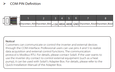
Just had a look in the Manual for Gen4, looks like this port. You will need to connect Pins 4 - 6 to your adaptor.
If you want to remove it from the Cloud remove your Pocket Lan.
Thank you!
I’m getting the impression that we’re at about the limit of what I can do. I’ve not no idea how I would connect pins 4-6 to anything. There are no cables coming out of that port on the Inverter and the port is covered over. I don’t think that I could connect anything else to my Virtual Machine as it is at the other end of the house and down a floor. The best bet for that would be ethernet, but £43 for a bit of kit that I don’t think I can set up might be pushing it a bit too far for my partner…she’s very accommodating but…
I really don’t understand why they don’t allow the Pocket LAN to work locally.
Thanks,
Tom
I’m using this one, purchased from
Here I can select what parameters I want and it will convert the rs485 modbus signal to ethernet.
I also needed a 120ohm resistor connected at the zlan terminals