Hi @CoTTeach,
According to the manual, Advanced SX unit has some port as well as USB, so maybe there is a way to connect to it. But it very likely uses other commands and it would require the whole sniffing the packets work (see Aelias’s work).
I would say Alextrical 's nor mine module will not work with Vent-axia Sentinel Kinetic Advanced SX unit.
Hi All.
Sorry for being AWOL on this project, I got hit by burnout and issues with ESPHome crashing on an ESP32 when processing the serial data input just killed my drive on this project…
I’m starting to think the Brain on the MVHR itself isn’t that well programmed, and trying to keep it in the loop is almost making more problems than it is solving.
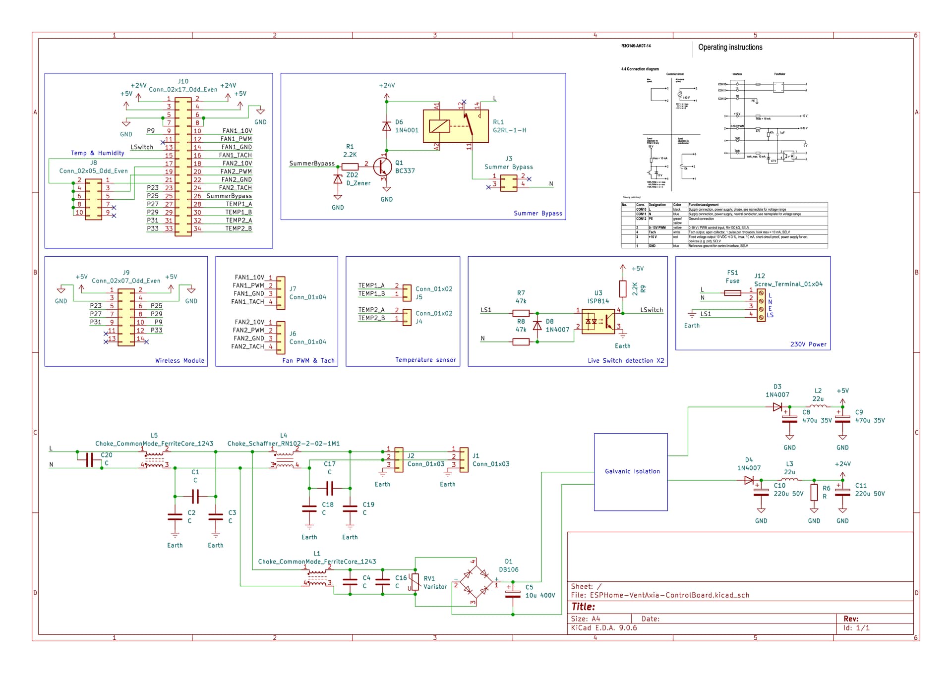
From investigation we have all the control of the unit going through the 34pin IDC. It would give us access to the following:
- PWM control over the FAN
- TACH feedback from the FAN (1 pulse per revolution)
- 2x NTC thermistors for inlet/outlet temp
- 1x Temp/Humidity sensor via I2C (AHT10/AHT20 IIRC)
- Switched Live sense
- Control over summer bypass (simple TTL on/off)
With this we can make a replacement control board, that would give us Full control over the entirity of the unit, and not have to deal with the odd decisions around Evening purge (just running at random times), though it would require some programming to recreate and implement the desired features.
The reverse engineered (partial, missing the PSU) schematic of the control board can be found attached.
Alternatively if we think the OEM Brain is good enough to communicate with over UART, we can connect to the second 34Pin header on the power board, to read out the Summer bypass state (TTL High is on/ Low is off), read the TACH from the motor to get a RPM)
Harder to achieve, but possible, would be to directly read the temperature/humidity, as we would need to sniff the I2C bus.
2 Likes
Out of curiosity, did you hit any issues with getting the ESP32 to handle processing of the serial data from the unit? I hit a wall getting the strings to process on my setup without causing the WDT to reset the unit IIRC.
Hi @Alextrical,
Welcome back ![]()
I’ve used your ESPHome component with modified timer and as far as i can tell i’m not getting any issues. My setup for testing is kind of janky at the moment as the MVHR unit is installed at remote location where i don’t live yet. It’s connected through 3G modem to my MQTT broker, so i don’t have full access to logs, but i haven’t noticed any resets or unresponsiveness for the time I’ve been testing it (3-4 weeks). How long does it take for you to crash it and reboot?
If you need help on the HW im happy to assist.
For the outputs, you dont need to use optocouplers for a dry contact. Its possible to control the SW1-4 simply by providing 5v TTL or pulling a pin to ground (depending on the exact SW number)
From my notes (5 months ago ![]() ) it looks like SW1-3 need to be supplied with a 5V input, SW4 is pulled up by the MVHR and needs to be pulled low to trigger
) it looks like SW1-3 need to be supplied with a 5V input, SW4 is pulled up by the MVHR and needs to be pulled low to trigger
Im hoping to get some motivation back towards working on this project over christmas. Im rally glad to see there has been some progress here while ive been away, good work ![]()
OOh, thats great to hear its not crashing. For my ESP32-Wroom it was an almost immediate thing. I should make up another module/unit and see if the issue still happens with that. Maybe it was a bad ESP32 module (that would be both great and annoying)
The only other issue i can remember was the control of the unit via 10V PWM. IIRC the LM324 i was trying to use made something have a whistling noise in use (possibly not playin nice with the Buck regulator?)
It should be possible to add ethernet by using a W5500 module https://www.aliexpress.com/item/1005007305875740.html
Of the top of my head i dont know if the vailable pins can be used for SPI, but i suspect it should be possible.
ESPHome already has support for that chip, so it shouldnt be too tricky to implement
I had encountered crashes when i was using Arduino hw-timer. After i did some cleanup and implemented only ESP-IDF timer it started to work correctly without crashing. Could this be the cause of your issues as well?
You are probably right. But it seems more safe to just short out + and - contacts of SW1-3 as those are already there and Optocouplers are not that expensive. Plus it is more isolated from the unit.
That adds points to my approach. By using SW1-3 it completely overrides unit’s behavior, so it won’t do anything you don’t want. I don’t think controlling the unit down to 1% results in better experience. It’s nice, but for most use-cases 3 modes are enough, so i skipped the whole proportional control
That could most likely be the same issue, I will have to look for your changes and see how you achieved that. Awesome work
I will see if i have any notes on SW1-4, but IIRC SW1-3 one pin is 5v common, and the signal pin is analogue 0-5V in
SW4 & SW5 is a resistor pullup to 5v on one pin, and the other is GND.
Opto’s are good for galvanic isolation, but we dont exactly need that in this situation, it also adds a somewhat bulky part to the PCB and needs redundant cables to be connected.
I will try to draft up a rough schematic from the control PCB
Ok this sounds really good. What would you say, an ESP32 is the new brain, connected to a custom board to plug things into? I agree we are pushing on a string with the current built-in controller and replacing it with something better would be awesome.
Something with a bit more capable means a lot of the functionality, sensors, calculations etc that more advanced systems have can become available to this. E.g. ability to do things like calculate the incoming relative humidity when that air is brought up to internal room temperature, custom fan profiles, options to add pressure sensors etc… I know, I’m getting ahead of myself ![]()
Even design choices like whether that switched live is needed… It becomes obsolete in a world where you have home assistant and ESP home providing software controlled switches and therefore don’t need to run wires across the house.
Anyway this has my vote! I’d certainly appreciate a board that can be populated and connected, some sort of standard ESP home configuration as a baseline, and all of the controls exposed to home assistant… Perfect.
Hi gyus,
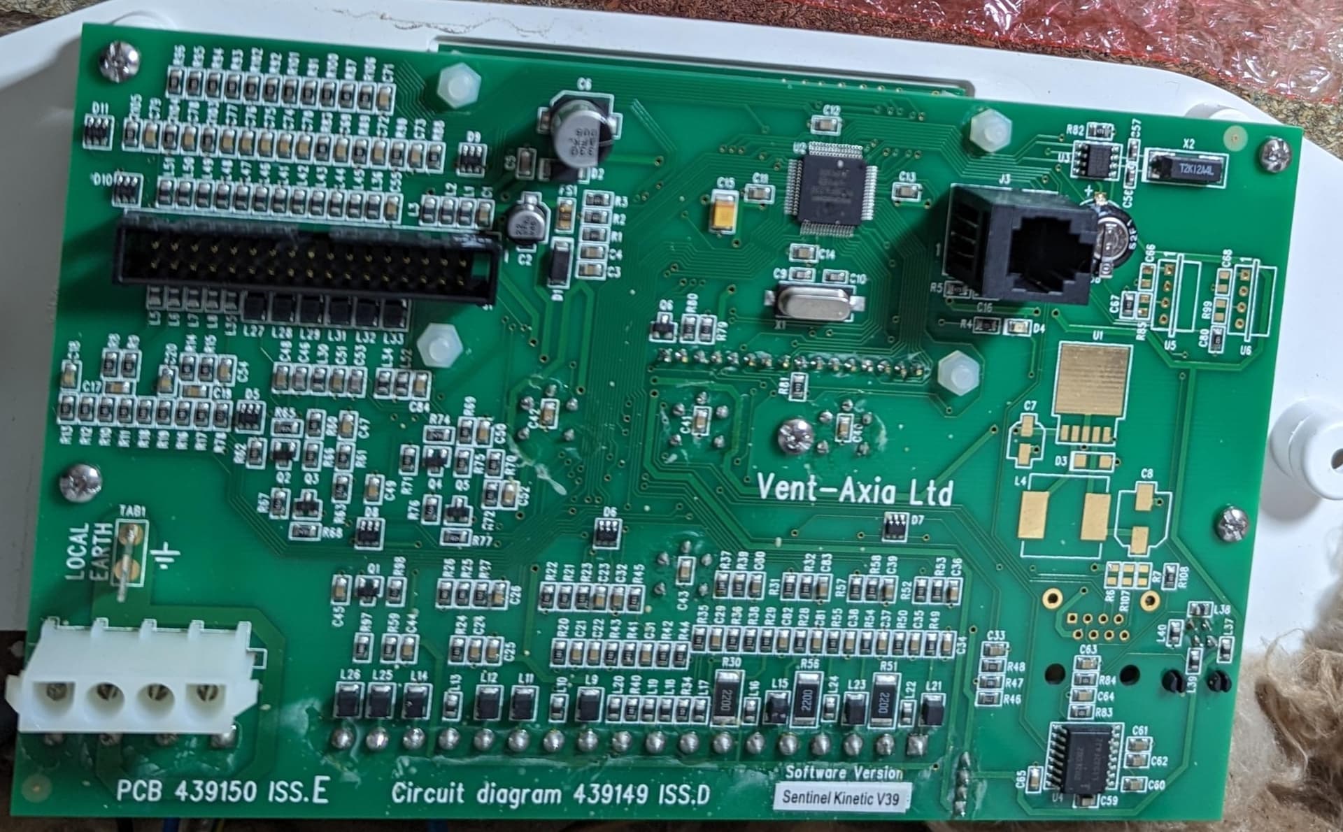
back in the day I was also looking into how to make the unit smarter and found out there are two versions of the PCB. One (older) have two PCBs connected via cables, one for “high voltage” stuff and second for the display. So in case of a older unit it may be possible to remove the display and create a custom ESP “new brain” that will connect to the second PCB and control the motors, bypass, etc…?
OLD:

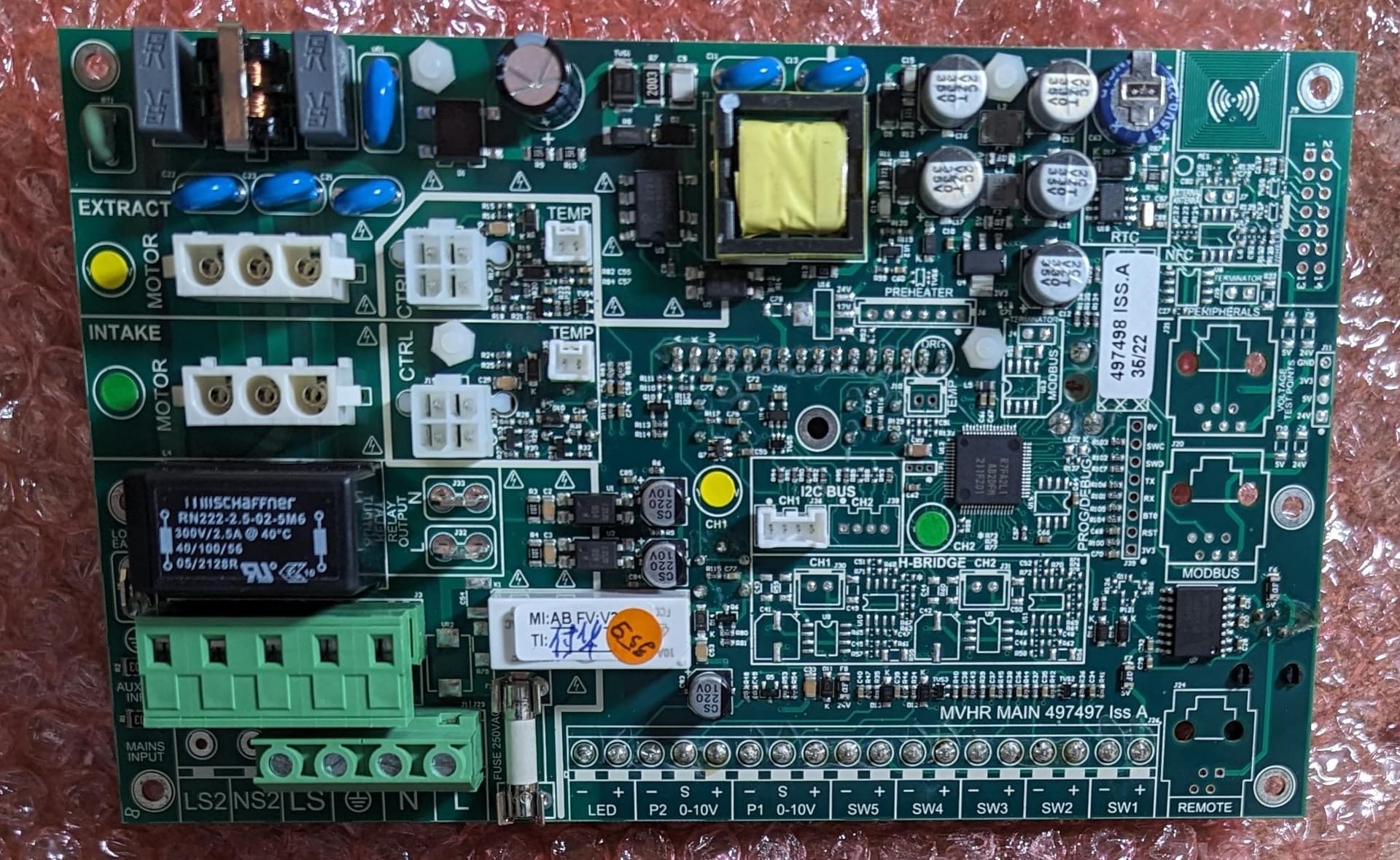
New revision have both parts integrated into one PCB I believe?:
That board looks pretty expensive to recreate, perhaps it’s too much? Are there any headers or pads we can access the main chip or ROM with? Maybe we can re-flash it?
Maybe it would be easier to wire in a ESP32 and use HA to control the switches on the board?
Yes, that was my thinking. Since on old revision the control board and power board are separated, then it should in theory be possible to hijack the power board and control it using ESP. On new revisions this is for sure much more complex as the PCBs are together in one.
I would absolutely love to buy a board that’s ready to be used with my MVHR! How do I do that?
I think me too. I currently have at least WeMos D1 Mini ESP8266 with small RS232 to TTL and thanks to your repo I was able to create at least remote controller to HA (currently instead of wired controller, it was in weird place and 2m of main unit anyway). For esphome 2025.11 and up there was change in BUTTON_SCHEMA so I at least created pull request which should work with newer versions (I got 2026.1.3). Including bubble cards I have pretty nice “HA remote controller”.

2 Likes
Same here. Any luck so far? Disappointing that Vent Axia have not yet done anything for HA integration, as it would be great to have a plug and play solution.
I’m also trying to do something with it and I am planning to add optocouplers to work with ESP2866 for SW1-4. According to VASK manual they can be used to control low/normal/boost mode (SW4 probably as cooker hood) in control mode 2. Also, there is P1 0-10V which can be used to manual control of fan speed - probably will try in “phase 3”.
Of course you will not be able to change settings by one click in the unit, but at least you can automate it better with HA with this approach.
I just installed a Shelly 0-10V G3 dimmer switch and hardwired it in the unit itself, so that I can turn the unit on/off remotely through S1 and have fan control via the P1 inputs. I have set the sentinel to run min 10% and max 90% and can now automate the control of the fan based on time, indoor humidity and air quality in HA. So far the setup has worked well and is probably one of the easiest and cheapest ways to take control of the Sentinel (£20 or so) if you want an easy option. You can also add a Plus plugin to the dimmer and add 4 DS18B20 probes and get temps of incoming/outgoing air etc as well. Haven’t done this yet myself, but plan to add these so I can monitor the unit temps as well.
2 Likes
Yes this is ideal… How is the 0-10V powered? Can you share the wiring setup please to the unit and the shelly?