I added a possible PCB. do you think it’s not good?
Can you give me links to the items I should buy?
I have an Arduino UNO and an Arduino Nano, but they don’t have wifi to control them with Home Assistant. I should add other components,
I added a possible PCB. do you think it’s not good?
Can you give me links to the items I should buy?
I have an Arduino UNO and an Arduino Nano, but they don’t have wifi to control them with Home Assistant. I should add other components,
You could wire pwm from your esphome to arduino analog input and scale it up to pwm output. Do you follow me?
Also serial communication between them is ok option, whatever is easier to you.
It’s good but not for positive side switching.
why do you say it doesn’t work? I control the fan with just one cable. if the variable voltage comes out of the negative, I use that
So why don’t you just connect it to gnd? 
Zero is zero pulsed or not…
Did you get this working?
Looking to buy the same lineup of vevor fans if I can get it to be controlled by HA
Hello Team trying to achieve the same did you manage to have it properly working ?
I have added my Vevor duct fan using this (same model as described in this thread):
output:
  - platform: ledc
    pin: GPIO2
    id: vevor
    frequency: 10000 Hz

fan:
  - platform: speed
    output: vevor
    name: Vevor varmeflytning
    speed_count: 10
Cutting the cable before the control display and connected the 24v and GND to a 24v to 5v step down module to power the ESP32. Yellow wire to PGIO2 and GND to GND on ESP32.
Only 24v and GND connected to the control display just to power it on.
If the yellow wire is not connected the fan runs at full speed.
All 10 step is equal to the fan speed from the smart display.
I tested this by setting fan speed to 100% and then removing the yellow wire from the ESP32. Fan does spins at same speed (MAX).
So even if the control display provide 0v - 5v for the 10 steps and the ESP32 provide 0v - 3.3v it spins at equal speed.
This is awesome!
Is the control display still required? Or is it possible to leave it disconnected?
The control display is not needed.
Awesome. Lets see if I can find this connector so I can keep everything original.
If anyone knows… 

On a first glance it looks like these: KPJX-PM-3S, but I’ll go and order the duct fan now.
I got this working without a level shifter and by just crimping my own 3 pin connector for where the display connector usually goes.
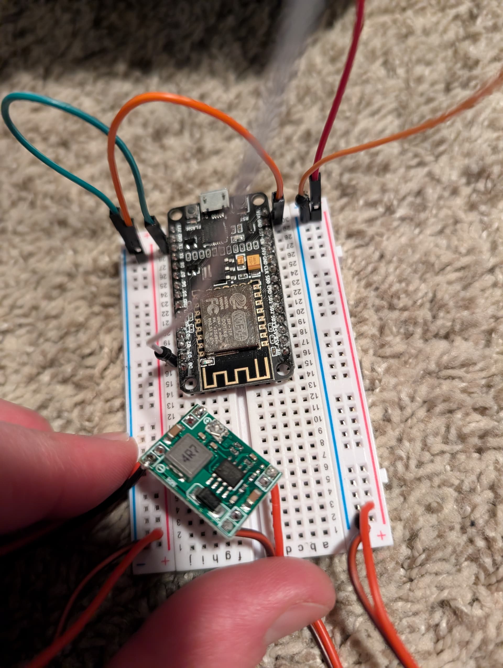
I’m using a 24V buck converter to step the control panel voltage down to 5V for the ESP and then just running the PWM fan control signal directly off pin D1. No level shifter required
output:
  - platform: esp8266_pwm
    id: fan_speed
    pin: GPIO5
    frequency: "10000 Hz"
    min_power: 0%
    max_power: 100%


fan:
  - platform: speed
    output: fan_speed
    name: fan speed
    id: fan_toggle
    speed_count: 10
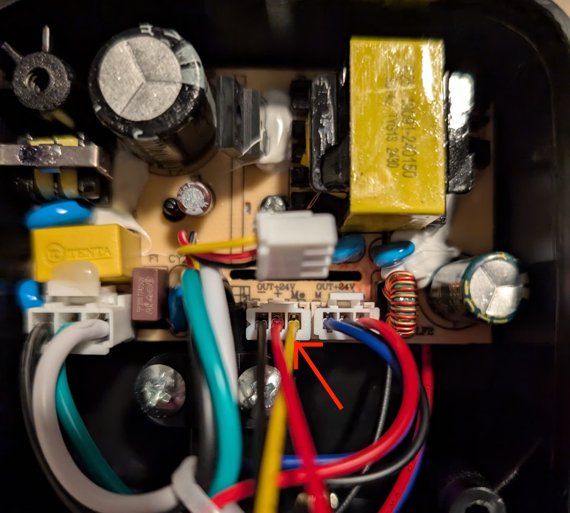
The yellow wire in the 1st image is connected to the white wire in the 2nd image. Power and Ground from the fan go into the 24V converter which then powers the ESP. Note that the ground is bonded all the way through on the converter which simplifies wiring a bit.
I also got this Vevor VV-GDFJ-EC8.
I was planning to control this fan directly from 4-pin fan connector, so i made some measurements with oscilloscope.
Measured betwene yellow and black, inside motor’s connection box.
It seems to be just like in this Intel spec sheet https://www.intel.com/content/dam/support/us/en/documents/intel-nuc/intel-4wire-pwm-fans-specs.pdf
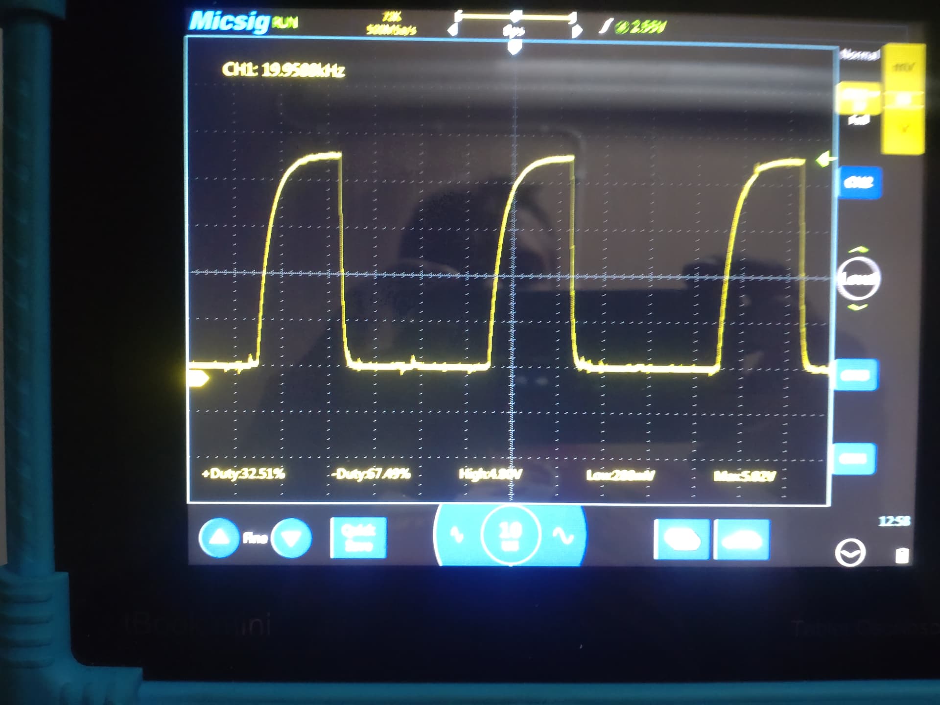
Measured 20kHz and 5V.
Speed setting - duty cycle%
1 - 25%
2 - 32%
3 - 41%
4 - 47%
5 - 54%
6 - 62%
7 - 69%
8 - 76%
9 - 88%
This is how signal looked like, speed setting 6
Speed setting 2
Then i measured my 4-pin fan, it showed 2,5kHz and duty cycle was inverted… Dont know what is wrong, it should be within specs also.
Im not so familiar with ESP boards, what would be good choice, it should be controlled via wifi and it has no other purpose than fan controller.
Hi, did anyone try to connect relay pins on the up/down button inputs of the panel? I like how it looks like so I’ll try to add this feature to keep manual operation, display and add wi-fi control possibility.
You might be able to do it without relays. Did you measure voltage on the button contacts?
I could but I have problems with opening the instrument case. Screws removed but I’m afraid I will brake it.
Then don’t open. Feed the pwm from the button panel to Esp as input and from there to fan.
Legend, this worked for me on a Vivosun G6 fan. I’m guesting they’re all the same underneath really. Since my fan has an EC controlled motor, i was able to add a lot more steps than the 10 standard that came with the remote which is a bonus too.
Care to share how you managed to do this?
Thanks