No clue mate, due to my lack of experience and expertise, i am just looking into problems as soon as they come up.
Never had to fiddle with that sensor before 
Hi Krash, just an update, I’ve decided to go your route and use the EspEasy firmware instead, I have it connected and hoping to conduct some testing to calibrate the meter. As I’m guessing you mentioned %value%/220 and 220 isn’t the default correct?
Exactly what i was referring to.
No, 220 isnt a default, it’s just a number i figured out by filling water bottles
Every liter was about 220-230 pulses on my sensor.
Some testing should tell you what the number you should use is.
Did you get it to work? Because i never managed to get a steady reading with it.
Having the same issue, working with the pulses seems to be giving inconsistent readings, with tasmota on the sonoff trying to use pulse timer, however cant seem to get the math working on Hass to calculate flow…
hoping some1 can shed some light on this? 
Found a non invasive possible alternative, if any1’s interested i posted a question here.
Would love any input.
Hey, im back on the project again ![]()
I managed to get it to work with the tasmota’d sonoff but had to do a little soldering 1st.
My waterflow sensor works with 5v in so, i had to get that from the chip by soldering a cable on the 5v pin on this picture:

Here is the final 5v out soldered:
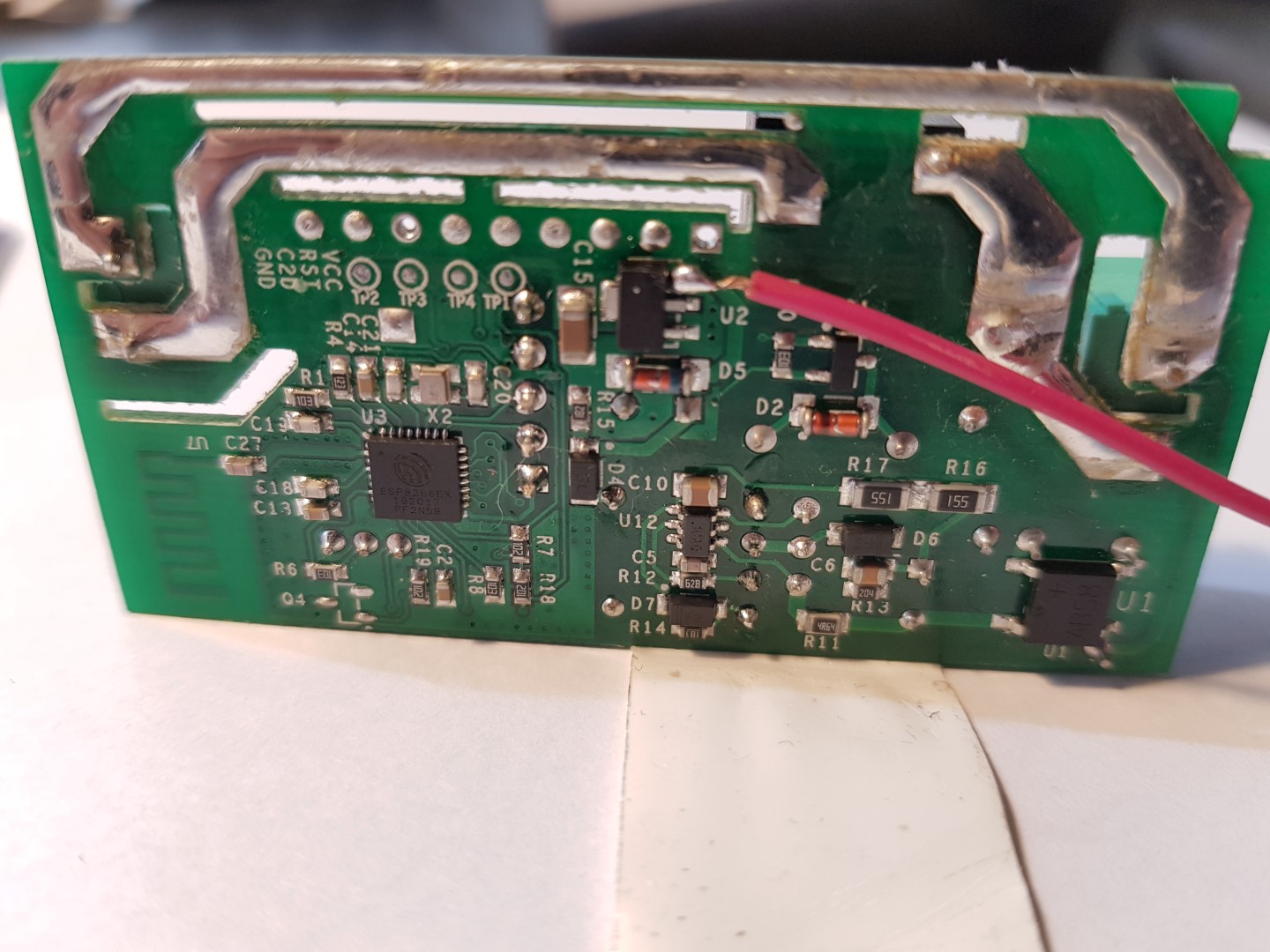
Routed the cable that way to avoid crossing the sonoff’s power rails:

And finally cut a small nick on the case to bring the cable where i wanted it. Again, i didnt use the little missing corner of the board to avoid running the little cable over the 230VAC power lines:

So now i get an increasing pulse counter:

It is not really accurate but, i think that’s the flow meter’s problem, when i fill in 1 liter with small flow i get a smaller reading than when i fill it at full flow of the tap.
That’s not a big problem for me as i want to keep track of the irrigation system in my country house remotely, to check for leaks and stuff, so i dont need great accuracy.
Now heading to do the HA part, ill keep you guys posted.
Update with HA code:
sensors.yaml:
  - platform: mqtt
    name: "water_meter"
    state_topic: "tele/sonoff_water_meter/SENSOR"
    value_template: "{{ value_json.Counter1 }}"
    unit_of_measurement: "Pulses"
And using a template sensor in order to make it read liters:
  - platform: template
    sensors:
      water_meter_liters:
        friendly_name: "Water Meter in Lt"
        unit_of_measurement: 'lt'
        value_template: "{{ (states('sensor.water_meter')|int *1/225) | round(2) }}"
        #The conversion rate is a result of testing, and not very accurate.
        #The round(2) is to only get two decimals at the end of the liter count.
I also made a script that would reset the Tasmota counter to 0, for future use in an automation:
scripts.yaml:
water_meter_reset:
  sequence:
    - service: shell_command.water_meter_reset
and shell_commands.yaml:
  water_meter_reset: 'curl http://sonoffIP/cm?cmnd=counter1%200'
  #that's command "counter1 0"
Now im working on a Trend binary sensor in order to know when the water is running or not:
binary_sensors.yaml:
  - platform: trend
    sensors:
      water_meter_running:
        entity_id: sensor.water_meter
        device_class: moisture
        max_samples: 2
        sample_duration: 30
It works half good, triggers when the water is running, but wont reset to off when the water stops, i must be doing something wrong. (posted about it here)
Will post further updates when any.
4 Likes
Nice work. How do how calculator a day usage?
I haven’t figured that out yet, but I think it would need some db manipulation, set a template sensor equal to to the value of the daily consumption then save it?
Haven’t looked into it tbh.
forgive me resurrecting the old thread, but didn’t wanted to open new with the problem that is touched here 
I just built a water meter with ESP (wemos) and two TCRT5000 (separate counters for house water and garden water) sensors. wemos flashed with latest tasmota. calibrated the TCRT5000 to properly react for reflective/non-reflective part of the watermeters’ rotating thingy, but still thinking how to make the readings more useable…
right now, depending on “the speed of flow” pulse count shows counts that vary a lot… a 3-digit reading when tap is fully opened and water flows like from fireman’s hose, and 5-digit output when slowly fulling up the bucket… so during my testing 1 liter equals to 552 (fast), or to 5297 (middle speed), or to 14616 (slow as hell)… tried to think out the solution like dividing it with time, or some constant-number but nothing worth trying pops up in my head.
did you managed to bite this problem somehow?
right now those readings are useable only as boolean - “water is opened” or “water is closed”, and of course that makes no sense for me
ok, so I’m going to make a little chit-chat with myself
I think I’ve found kinda simple solution, but still struggling to get it work [I need to read more on tasmota’s commands and rules]. the plan is:
- set the TCRT5000 sensors as switches
- set two additional counters assigned to pins that are not used in wemos
- set up tasmota rules, with the trigger “sensor state = OFF” and action “increase counter” [of course twice, with corresponding sensor and counter numbers], and publish the counters via MQTT
right now I’m stuck on the rule construction [but just started it, and while I found out about rules “5 minutes ago”, I hope that it’s just a matter of reading the guide/tutorial/wiki etc.]. if anyone wants to contribute or point me to better direction - you’re welcome to do so!
Hey there,
So let me get this straight, your water meter has some rotating thingy that reflects light and the TCRT5000 counts these pulses. This sounds very interesting. Here are my thoughts, and sorry if im missing something, i might be completely wrong:
It sounds to me, though, like it is not very accurate like it has some maximum pulses per given time that it can read. I mean, the more time the water flows, the more this thing registers pulses. Seemingly unrelated to the actual pulses. Try to test it for a specific amount of time, with different water flows like, 20 sec with small/medium/max flow and see the results.
As i said above i had some inconsistencies while trying to measure the number of pulses per liter it was like 221-228 or something (and completely different identical counter that i tried on another project, around 340).
Your value differentiation makes me think that something is not working correctly.
On the tasmota firmware, i dont quite get what you are trying to do. Why the workaround with switches and counters and not directly counter?
hi!
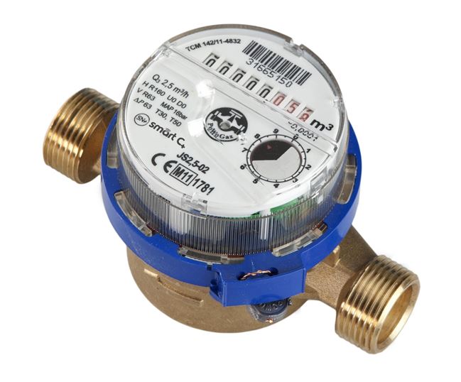
check out this photo - the clock-dial-looking disc in the right part of the meter is the silver-metal rotating-thing I was talking about the black part blocks light from TCRT5000.
about the pulses used in the “counter” setting.
I was able to calibrate the sensor - as you can see, it has a little screw on it - to react appropriately to the spinning disc, but even then it’s reaction is [as far as I’ve noticed] based not only on “light interruption” but also on “time of the interruption/reflection”. I know that there’re debounce settings in tasmota, which might help a little, but unfortunately I think that I cannot bypass this incosistency while metering. not with my knowledge at least [I’m mostly a copy-paste programmer ;)]. if it would be something like yours 221-228 pulses, I’d be happy to use it, it would be almost perfect to estimate.
now about my “workaround”.
I figured it out, that if “counter” combines pulse and time; while the “switch” uses only two states - then maybe it’s the way to go. sure, with faster flow the ON/OFF are not very “real time” but I noticed, that somehow they are queued and seems like tasmota shows them all, but with the slight delay [understandable for me]. I know, that I could use HomeAssistant to count these ON/OFFS and make a counter inside HA, but that would double the delay IMO: sensor->tasmota->mqtt->homeassistant. too many places that could fail.
if I combine it on the tasmota side only I’m not only cutting off those additional parts from the equation, but also I have an opportunity to save the counter into “ESP’s memory” to keep it safe in case of some network/power issues [well, I mean: I’m wondering theorethically, something similar popped up somewhere on the tasmota website].
of course: I can be soooo wrong with my plan, but right now it’s all I’ve got
today after work I’ll probably start to read more about tasmota rules, so I could build a proper one and test my theory in real world. I am aware, that this method could be also very buggy or it would introduce couple of other problems/delays/inconsistencies - but like I wrote - it’s all that my partial knowledge could cook right now
Got it, mines are the same.
Me too ![]()
I don’t know about this, i haven’t noticed this with my counters (the principal is the same as the counter i use is also sending pulses, which the tasmota is adding up).
To be honest, i started messing with the pulse counter before i got into the tasmota/home assistant game. First time i set it up i had a python script (i think) that would add the pulses. Ill see if i can find that script somewhere in my back ups, maybe you can copy/paste it and it can help you figure it out what exactly is going on.
edit1: i mean, the first thing you should make sure is that one turn of the meter is registered as one pulse on the sensor. Else everything else after that will fail (unless you just want to monitor on/off and dont care about the rate/consumption)
edit2;
Found the block of code, you ll have to change your gpio number and confirm the naming, also you ll need to see if it’s a pull_up or pull_dn.
Hope you know what to do with this, as i’ve used it about a year a go and cant remember how to help you if needed ![]()
#!/usr/bin/env python

import RPi.GPIO as GPIO
import time, sys

FLOW_SENSOR = 5

GPIO.setmode(GPIO.BCM)
GPIO.setup(FLOW_SENSOR, GPIO.IN, pull_up_down = GPIO.PUD_UP)

global count
count = 0
previous = 0

def countPulse(channel):
   global count
   count = count+1
   # print (count)

GPIO.add_event_detect(FLOW_SENSOR, GPIO.FALLING, callback=countPulse)

while True:
    try:
        time.sleep(0.05)
        if (count > previous):
          print(count)
          previous = count
    except KeyboardInterrupt:
        print ('\ncaught keyboard interrupt!, bye')
        GPIO.cleanup()
        sys.exit()
edit3:
Wait, dont bother with the python mess… can you hook up the counter directly on the pi?
At least for troubleshooting.
If so, you can use a Raspberry Pi GPIO Binary Sensor and set up the sensor directly on the HA bypassing the tasmota.
I think that would give you some insight as to how the sensor is registering ons and offs by avoiding any tasmota delays.
Sorry i might just be mumbling and getting you into worst trouble ![]() someone with more experience should step in and stop me
someone with more experience should step in and stop me ![]()
1 Like
so, you’re telling me that I’ll have to learn how to copy-paste python now? ![]() I was afraid that this time will come sooner or later…
I was afraid that this time will come sooner or later… ![]()
this is where I couldn’t find any solution. I started to think that maybe the plastic transparent cover on the meter is somehow distracting the led and confuses pulse count… but even if I tried with something else [I prepared a piece of wood with reflective foil and black painting to simulate the meter ;)] it still was with the same results. or maybe me calibrating the screw wasn’t as precise as should.
omg, in the meantime you’ve found the code. THANKS!
don’t know what to do with it yet, but hoping to figure it out at the evening ![]()
do I understand it correctly, that the python script assumes the sensor is connected to RPi?
…aaaaand that’s a great edit ![]() good thing I was still writing my answer
good thing I was still writing my answer ![]()
sure, I’ve got some other Raspberries somewhere around to test it, not sure if it will help with configuring tasmota then, but at least like you wrote - I’ll be able to check the sensor weakness maybe.
I’ll keep this topic updated in case I figure something out!
hahaha, i feel you getting to all this trouble! justto finally realize that the the sensor is china-defective ![]()
Yup, it’s got vcc/gnd and the signal wire went to gpio #5 (as you see, im using setmode(GPIO.BCM) so you ll need to find a BCM gpio map to see which one is gpio5 or set the appropriate number.
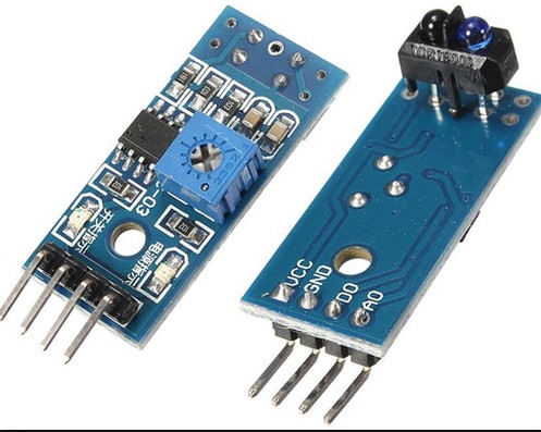
BTW, why does your sensor have two signal pins? does one send on/off and the other is supposed to be connected differently?
–quick google search–
Yup, that’s it, you have it connected on the DO right?
The DO should give 0/1 and the AO (analog output) will give low values on detection and high values when nothing’s detected, according to this guy:

Also, scrap the “connect the sensor to the rpi” idea, the sensor has an indicator led, that could help you see if its reading the changes correctly, no?

Manually check if the led flashes once every turn of the meter?
Like on while white, off while black? then go on from there ![]()
just a quick reply to confirm: yes, before mounting on the meter I was testing with the LEDs only (one shows “power is on”, second detects state) - and all is fine. LEDs are reacting way they should - it helped me to calibrate the sensor (to find the sweet spot, when sensor reacts at silver part and turnes off for black one). also: depending on sensitivity setting, keeping the signal led turned on (meaning: moving something reflective next to the sensor) makes counter to increase just a little or lots of - more sensitive setting gave me tens of counter-points when moved finger/my wooden simulator; and less sensitive setting gave me just a few points after waving the same thing with the same speed - that’s I moved to ON/OFF readouts.
the sensor LEDs on the other side are indeed an “emmiter” and “reader” so to speak.
after “few days” of delay, I had a moment to look again on my ideas and… solution was really simple, I just have to check all the readouts on meters, and enter everything into “production device”, right now tested on another wemos and looks like it’s working the way I was thinking of.
so, my sensor is connected to D1 pin on my wemos board & is configured as Switch1; then Counter1 is selected on other, unused pin [in my case: D5] - it’s just a placeholder for numbers.
then, in the tasmota’s console, I’ve entered:
switchmode1 1
counter1 <enter-initial-counter-value-here>
rule1 on switch1#state=0 do Counter1 +1 endon
rule1 5
rule1 1
after that, every sensor “blink” [which is understood as toggle: OFF->ON] increases counter1 by value of 1.
so, other way than the standard pulse-count, it counts every blink as one and not as a few or even more like before. I don’t have to save anything anywhere, as the count is preserved after esp reset.
tomorrow I’ll start “daily driver tests” with the right wemos board mounted on water meters and I’ll see if there is any miscalculation with the measured liters.
2 Likes
Good morning, seen following in this discussion because I’m interested in progress, my current situation is as follows: I have a water tank that I fill with a well, at this moment I installed a water flow sensor (FL-808) and a sensor Ultrasound built by me with a nodemcu and firmware ESPEASY I am attaching a sketch. currently I have the exact measure of the level of filling by means of ultrasound and the fall of the water but the problem that I only measure the liters per minute but I can not find the solution to have a total of liters taken. I am attaching some photos.


in the yellow circle is the flow of water (liters per minute) and it’s ok, in the red circle is water level inside the tank and it’s ok, and last in the blue circle I would create the total liters of water taken … I really hope to succeed … also thanks to your help …