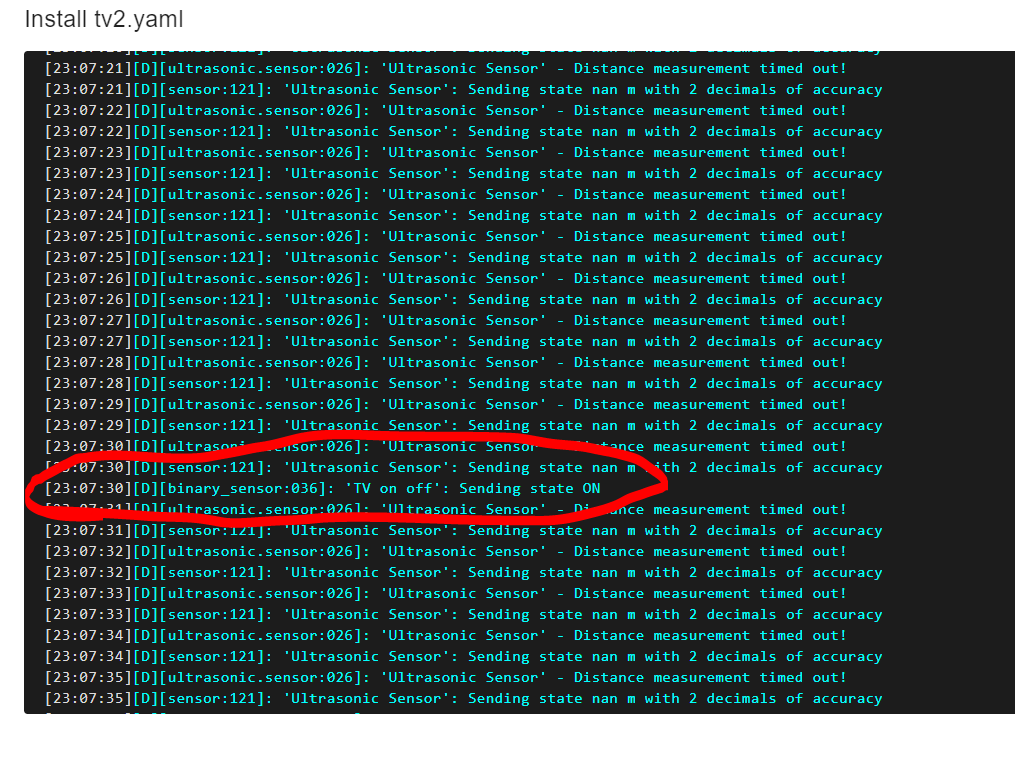
It looks like nothing is being logged in your pic, perhaps because it’s not booting. You can see in my boot alot is logged before getting to binary sensor. This is a ESP32 board.
I’m using Esphome 21.9.3. Are you using an older version? You should be able to select a specific board.
I tried to create a new device and it worked fine.
I added the binary sensor only to the configuration.
It worked, it connected and everything looks fine. (haven’t tried the actual sensor though)
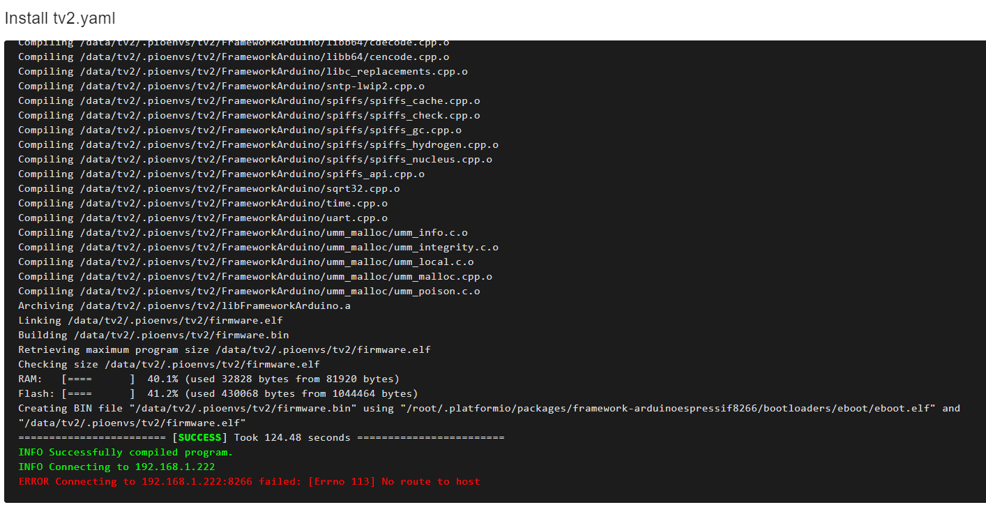
Then I added the rest of the configuration and opted for OTA and it can’t connect anymore.
If I click logs I see this:
If it’s still not working with nodemcu board selected , then perhaps with dfsplayer added ,it uses up more flash memory than the nodemu has. If you click install but then select download it will give you a .bin file ,which size may be too large.
I tried again to start from scratch, and I skipped the step and selected nodemcu, then compiled and installed via “new” way.
It connected fine and then I added the binary sensor, still fine.
Added the rest of the config and got this:
It gives an IP which suggest its trying to connect over network rather than directly. Just double checking you created a .bin file to flash from. It sounds like we are so close now to getting it to work.
I updated ESP-Home.
I created the device from scratch, pressed skip this step and selected nodemcu.
I then flashed this “blank” config to the device via cable and ESP-Home.
Then I added the rest of the configuration and flashed again via cable and ESP-Home.
I tried to make a change and flashed again via OTA and it worked too.
It’s nothing groundbreaking that I did differently from the other (feels like) 50 times, but I think it could be that I selected nodemcu and not just opted to let ESP-Home select.
And that I flashed a “blank” config first. Most of the other times I have tried to add some of the config from the start.
Finally it’s bedtime!
Oh… and can a board like this be flashed without the USB port?
One board got damaged from today’s excessive flashing.
Is there any pins that you can connect a TTL flasher on?
Should be able to tell uart pins from the pin out diagram. May have to put it into boot mode by pressing the boot button as you turn it on to get into flash mode.
Don’t forget there are a lot of faked chips/boards out there. I bought some supposedly d1 mini pros. Well, they had the external antenna connector, but not the extra flash.
That is definitely NOT a ESP01, it’s a NodeMCU (or copy of sorts) just going by the photo. That’s why you can’t select a PIN that doesn’t exist on an ESP01.
Well, how do you then explain that it had no issue with GPIO12 and GPIO14?
I have never had any issues with just going with what EPS-Home has given me before.
A few months ago then it was more obvious that you selected the board.
In my opinion the installation guide is confusing at best.
Why would I have to click on “skip this step”, meaning I want to install it later to be able to select the board type?
Why is there no, “install now but let me select the correct board” if it matters this much?
I dont have the answers you are looking for. But this method is from what I understand pretty new. It is still being developed and improved. There might be some hickups or illogical things.
Your feedback is usefull to give.
I cant explain it. GPIO12 and 14 simply dont exist on an esp01 or esp01-1m board.
Maybe the code was sound, and this pin-error is not caught (yet). Therefore you dont see an error message. But maybe it just wont work becuase the selected board is not allowed to output on that pin. But I am just guessing here.
BUT. You have it working now. Despite the installation guide