Hallo @FredTheFrog ,
auch dir einen wunderschönen guten Abend…
I tried it before. Same problem. :
I’ve updated the component with keypad support. You need to import more components now. See the README.
Update :
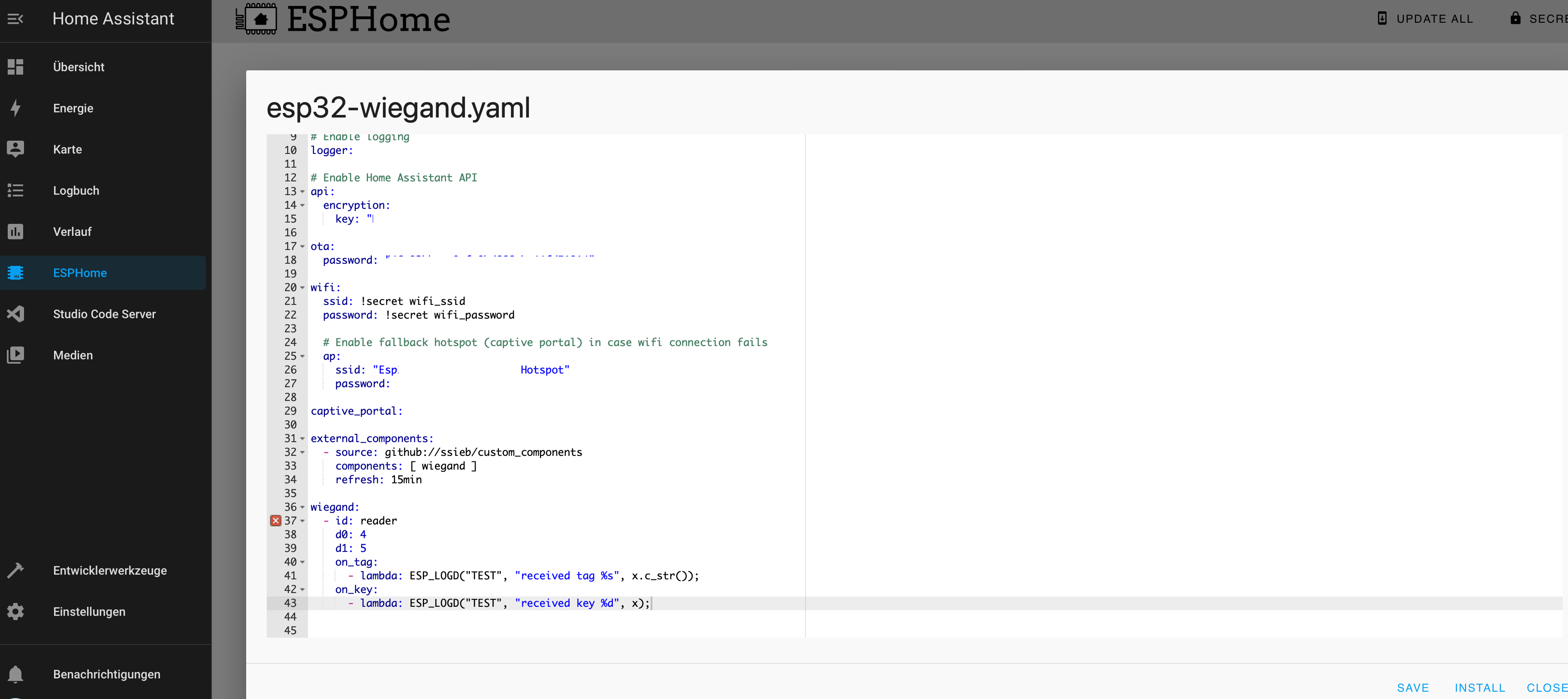
some custom components are working without an error and some do not.
Here is an example for a working one.
You picked the one that literally crashes the device as the working one? 
But why are you asking about this here? The topic is Wiegand readers. If that component isn’t working, then it might be relevant to ask here. But if other components aren’t working, then you should file an issue on the repo or come find me on the esphome Discord server.
Hi, I’m building a new house and excited at the idea of integrating this, using it to trigger an electric door strike.
I haven’t gone through the project in detail, but I’m at the point of pre-wiring the house now. What do I need to plan for? Just 12v power beside the door frame?
I’m not to familiar with ESPHome, is there any reasonable way to adapt this to a fully wired solution? I’d prefer to not lose access if my wifi network goes down. I noticed this, does it mean I can do wired eithernet with ESP32? Would it conflict with this project?
Thanks!
David
devices will work without internet. any device on esphome can be standalone and work.
and yes you need 12v only you need to understand that the esp and components work from 5v. they need a step down converter. I made such a project at work but on a simple rfid reader
devices will work without internet. any device on esphome can be standalone and work.
Ok but what about other failure modes? If the link to homesassistant is down, or homeassistant itself is down, I’d still like my door access to function. I guess that would mean this device needs to keep a cache of authorized hashes and also be able to directly switch the relay connected to the door strike. I don’t think this project does that already but might be a cool extension.
Most Wiegand tag readers include several wires in the bundle, where some connect to the ESP microprocessor (green and white, the two DATA lines), others connect to the 5VDC power supply (Vin/red and GND/black), while two others serve to change the color of the LED on the reader or to beep the beeper/buzzer on the reader. These two lines typically react when connected to the GND ground connection point, FYI.
Using a combination two-relay or four-relay board with embedded ESP microprocessor, you can save some wiring effort. These boards are typically used for sprinkler controllers or lighting controllers, or even gate/latch/hasp controllers. If you hard-code a list of two or three or four tag IDs in your ESPHome YAML, then your device can function to open/unlock/lock even if the LAN or Home Assistant server is down or offline.
Thanks, this is a great idea.
To be clear, the ESP will need to be located fairly close to the reader, right? Or are the green and white data lines capable of being driven 20-30ft so I can put the ESP out of the way in my IT closet?
EDIT: Currently I’m prewiring my house which has open walls, trying to figure out if I should run CAT6A to the door, or something else to support this.
Yes, the ESP board needs to be physically close to the reader. The D0 and D1 (green and white) data lines carry 3.3VDC or 5VDC signals and just won’t travel too terribly far. I’d keep the ESP relay board within ten or fifteen feet at most and use good quality stranded 22AWG or 24AWG 100% copper wire for the connections. At my home, I used a small plastic project box on the reverse side of the steel-framed exterior door. This kept the connections short enough for the wire/pigtail from the reader to connect directly to the ESP. For security/hardening, I’d typically place the ESP board a few feet away, preferably in a non-visible location, and hide the wiring behind the sheet rock or paneling.
If you switch 12VDC through the relays to operate your lock/hasp, that can travel a good bit further, and typically requires thicker wire, 18AWG or possibly 20AWG.
Cool, thanks for confirming. I have a closet for jackets/boots right near the front door which could house a little project box. I’m thinking I’ll run CAT6A (to carry POE) to there from my IT closet, assuming I can easily step down to 5V and [12V or 24V] and then run to the reader/door lock from there.
I use the typical 12VDC 3A power brick/wall-wart, chop the end/barrel connector off, and wire it to a couple of places:
The +5VDC out from the buck convertor goes to the ESP/relay board.
The +12VDC from the wall-wart goes to the Wiegand reader
The GND/ground is common to the ESP, the Wiegand reader, and the wall-wart.
Hi, nice work.
maybe it’s an idea to use transistors instead of relays for led control to reduce size?
it’s possible to use a D1 mini breadboard shield
https://a.aliexpress.com/_EItBGaD
and make following circuit on it.
probably the pull-up isn’t needed if the wiegand module has an internal pullup.
I got my hikvision ds-K1101MK working 
I was wondering if this is a secure way to disarm an alarm with an NFC tag.
Is it just sending the batch ID? If so, isn’t that readable for any NFC reader and not protected against cloning?
If you leave your fob where somebody can clone it, yup, it’s not a secure way to disarm your alarm. Mine is on my car keys, and never leaves my pocket until I return home.
Yes u have a point.
I have my keypad working but the individual keystrokes are registered as tag_scanned on the event bus.
Is there an easy solution to form a pincode with it?
Maybe start an automation when i press the ‘*’ key? But then i cant use the tag_scanned event in the conditions section to scheck a sequence.
The guy who wrote the custom component is an absolute hero!
He has a component for what you requested - here is how i do it:
wiegand:
  - id: reader
    d0: 25
    d1: 27
    on_tag:
      - lambda: ESP_LOGD("TEST", "xreceived tag %s", x.c_str());
      - lambda: id(handle_input).execute(("CARD:" + x).c_str());
    #on_key:
    #  - lambda: ESP_LOGD("TEST", "received key %d", x);

key_collector:
  - id: pin_reader
    source_id: reader
    min_length: 4
    max_length: 8
    end_keys: "#"
    end_key_required: true   # default is false
    back_keys: "*"
    timeout: 5s
    allowed_keys: "0123456789"  # if not included, then any otherwise unused keys will be allowed
    on_result:
      - logger.log:
          format: "input result: '%s', started by '%c', ended by '%c'"
          args: [ 'x.c_str()', 'start', 'end' ]
      - lambda: id(handle_input).execute(("PIN:" + x).c_str());
only one thing - right now this seems broken due to a compile error - that would be the fix:
Hi
In the log I see the read RFID TAG. But it doesn’t arrive in IOBroker ESPHOME Device. In the MQTT device I only see the message in the debug. How do I get the TAG in the ESPHomeDevice
external_components:
  source:
    type: git
    url: https://github.com/ssieb/custom_components
  components: [wiegand, key_provider]

wiegand:
  - id: reader
    d0: D1
    d1: D2
    on_tag:
      - lambda: ESP_LOGD("TEST", "received tag %s", x.c_str());
    on_key:
      - lambda: ESP_LOGD("TEST", "received key %d", x);
ESPHOME Log
[17:25:53][V][wiegand.text_sensor:048]: received 26-bit value: 22efc4e
[17:25:53][D][wiegand.text_sensor:051]: received 26-bit tag: 1539623
[17:25:53][D][TEST:145]: received tag 1539623

MQTT Device debug
[0;36m[D][TEST:145]: received tag 1539623 [0m
I tried it like this and it works
text_sensor:
  - platform: template
    name: "RFID Tag"
    id: rfid_tag

wiegand:
  - id: reader
    d0: D1
    d1: D2
    on_tag:
      - lambda: ESP_LOGD("TEST", "received tag %s", x.c_str());
      - text_sensor.template.publish:
          id: rfid_tag
          state: !lambda 'return x;'
    on_key:
      - lambda: ESP_LOGD("TEST", "received key %d", x);