Thanks for the update! This one was very interesting! Really wants me to change my system also to unipi.
1 Like
A post on the unipi hardware platform, mostly what it is and how it fits my installation: Hardware
1 Like
The input modules you used are back in stock!
I did mention the Neuron M303 in my post, but I actually did use the L303 (Unipi Neuron L303 | Unipi) which is discontinued.
Thanks for pointing it out! I did update the post with a link to the discontinued L303.
A post explaining the software used in my setup: Software
2 Likes
Final post in the series, this time it’s about home assistant; Service
Includes some functioning sample docker-compose and home assistant config files to get a feel for the setup I use.
1 Like
@mhemeryck great and helpful posts! I’m looking forward to next articles, especially about security and reliability.
Thank you for your time.
I plan to proceed very similarly, maybe just like you. My physical wiring is almost the same like yours. Couple a days ago I finally connected wiring to my Unipi Patron (switches and external relays).
2 Likes
Nice to hear!
I think my setup is a bit different in that for the lights, I just have the lights directly connected to the unipi relays – it seems in your case, you have a set of other relays between the lights and the unipi unit. For my blinds I did something similar, since I didn’t want to connect a motor directly to the unipi relays (actually, one of the relays actually got stuck after an issue with the blinds  triggering me to reconsider the setup and indeed putting an extra set of relays in between).
Another difference is that you seems to be using a single unipi unit for both input and output. In my case, I have one for all of the inputs and another for all of the lights. What kind of software are you using, i.e. how do you program which input controls the outputs?
For software part I plan to use mainly Home Assistant (on RPi4) + MQTT and Evok on unipi with Node-RED OS.
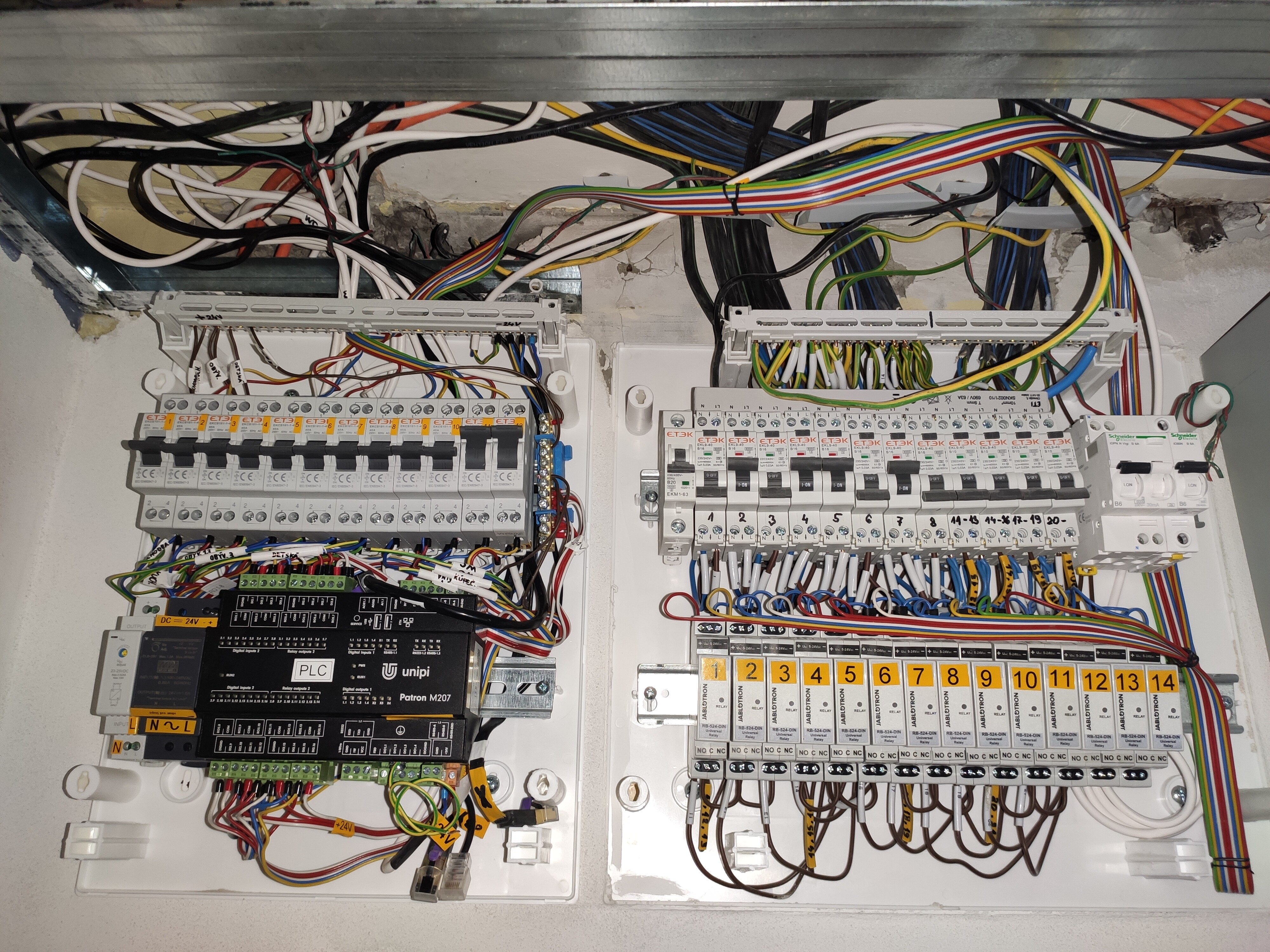
And yes, I have an external set of 24V DC relays (on right bottom DIN rail) with separate 24V power supply. Another 24V power supply is dedicated only for unipi.
Above unipi (left top DIN) is set of switches with 3 states ON-OFF-ON in order to get +24V to external relays from:
• 1) wall switches
• 2) OFF (nowhere)
• 3) unipi RO
Reason was to make better resiliency - eliminate single point of failure - unipi and make possible to control lights directly with wall switches.
@mhemeryck do you use also analog I/O somehow? I would like to do simple energy (current) monitoring in future…
1 Like
I haven’t been the analog I/O thus far. I did buy a 0/10V analog water tank level sensor a while ago to read out using the analog I/O. However, I haven’t had the time yet to work on this, plus the instruction manual that came along with it was in Chinese, including the notes on the wiring color coding ![]() .
.
how did you connect arduino with Home-assistant?
i’m new on this forum…can you show something more on you project please?
I would like to create a minimally invasive system, in case the home automation should break I have to be able to use the house normally, like in any case performing all the main functions normally, such as turning on the lights etc …
tnx on advance!
I didn’t use arduino; I did use a hardware platform called unipi.
See my blog posts for more info.
It’s been a while since I’ve worked on it and overall, it works quite OK. Given I would start again though, I might reconsider some off the shelf hardware setup though, like loxone, or NIko (which is quite a well-known brand in my area).
@mhemeryck reorganised his blog and so the links are broken. Why (which has links to the other posts at the bottom too)
Thank you for pointing that out. I indeed change the blogging engine, so links might have been broken. The introductory post Why - should have all the correct links though.