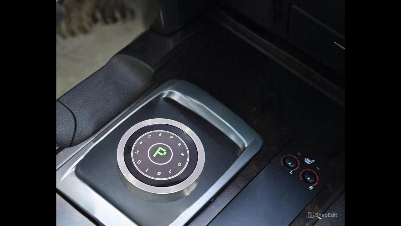
1.28 inch 240*240 ESP32C3 Round Display with Rotary Knob UEDX24240013-MD50E by VIEWE company

Recently, for my DIY project aimed at “smartifying” a kitchen hood integrated with the apartment’s general ventilation system, I purchased a round display with a rotary encoder based on the ESP32C3. The idea is to add remote control, monitoring, and automation for the hood itself, while also implementing a shutdown timer and additional control over the rest of the ventilation system directly from the hood.

The project is still in progress, but I liked the display so much that I decided to share my experience with the ESPHome community and provide a couple of templates for inclusion to ESPHome and Homeassistant.

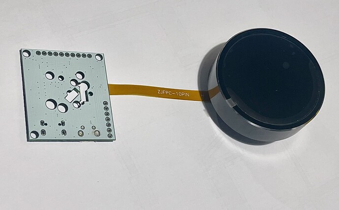
Device pictures:


This display is available on AliExpress for less than $25. It is based on the ESP32C3 chip and features a round IPS display with a 240x240 resolution, a GC9A01A display driver with LVGL support, PWM-controllable backlight, and an aluminum rotary encoder knob around the display with a push button function.

The display should be powered by 5V and connected via a 10-pin FPC flat cable. It comes with a development breakout board that includes a micro-USB socket and pinholes for connecting external power and accessing GPIO pins.

This dev board appears to be unified for different display types, as it has two sockets for FPC cables and provides some additional pins that are not used by this specific display. However, the easy access to GND, 5V power, and 3 unused GPIO pins (GPIO03 ADC, GPIO20 RX, and GPIO21 TX) for connecting additional components like sensors is very convenient.

The build and material quality are very high. It looks great, and the knob has a satisfying tactile feedback. The display is bright with wide viewing angles. While this product does not have a touch screen, for such a compact size, it is not necessary, as the encoder knob is sufficient.

Aliexpress (manufacturer shop)

https://www.aliexpress.com/item/1005007045539218.html

*WARNING: *
There is another and bigger (2.1 inch) round display from the same manufacturer, but it has different display driver chip, which at the moment is not supported by ESPHome! But is still supported by Arduino and ESP32-IDF.

I couldn’t find any information or examples on how to connect this device to ESPHome, but the manufacturer provides documentation and examples for Arduino and ESP32-IDF. Using that information to learn more about the chip and pin configuration, I created two templates for connecting it to ESPHome. The first template is basic, while the second one enables LVGL support. For quick testing, I added test pattern outputs to the screen and embedded web server to check all other components in both templates.

Basic template:

esphome:
  name: knob-display-basic-template
  friendly_name: knob-display-basic-template

esp32:
  board: esp32-c3-devkitm-1
  framework:
    type: arduino

# Enable logging
logger:

# Enable Home Assistant API
api:
  encryption:
    key: "YOUR_API_KEY_HERE"

ota:
  platform: esphome
  password: "YOUR_OTA_PASSWORD_HERE"

wifi:
  networks:
    - ssid: !secret wifi_ssid
      password: !secret wifi_password
    - ssid:  "YOUR_SSID_HERE"
      password: "YOUR_WIFI_PASSWORD_HERE"

  ap:
    ssid: "Esp32C3-Knob-Display"
    password: "AP_PASSWORD_HERE"

captive_portal:

web_server:

# SPI configuration
spi:
  id: spi_bus
  clk_pin: 1
  mosi_pin: 0

# Configure the display
# remove 'show_test_card: true' option or set it False to disable test pattern
display:
  - platform: ili9xxx
    model: GC9A01A
    cs_pin: 10
    dc_pin: 4
    reset_pin: 2
    rotation: 0
    id: round_display
    spi_id: spi_bus
    invert_colors: true
    show_test_card: true 

# Backlight control using LEDC output
output:
  - platform: ledc
    id: backlight_output
    inverted: True
    pin: 8
    frequency: 5000Hz

light:
  - platform: monochromatic
    name: "Display Backlight"
    output: backlight_output
    restore_mode: RESTORE_DEFAULT_ON

# Rotary encoder configuration
sensor:
  - platform: rotary_encoder
    id: my_rotary_encoder
    name: "Rotary Encoder"
    pin_a: 6
    pin_b: 7
    resolution: 2

binary_sensor:
  - platform: gpio
    id: encoder_button
    pin: 
      number: 9
      inverted: true
    name: "Rotary Encoder Button"
    filters:
      - delayed_on: 50ms
      - delayed_off: 50ms

If you have difficulties switching the module BOOT mode for initial ESPHome flashing, you can use the following workaround:

  • open ESP Tool in a separate tab of the same Chrome browser with device connected to USB port
  • click on Connect button under the Program block
  • once device is booted in flash mode click Disconnect
  • switch back to the ESPHome Dashboard tab and proceed with initial ESPHome compilation and flashing by using local USB port

Here is how it looks like after flashing basic template:

LVGL template:

It is almost the same as basic, just has additional empty ‘lvgl’ section and two additional required parameters in ‘display’ section

esphome:
  name: knob-display-lvgl-template
  friendly_name: knob-display-lvgl-template

esp32:
  board: esp32-c3-devkitm-1
  framework:
    type: arduino

# Enable logging
logger:

# Enable Home Assistant API
api:
  encryption:
    key: "YOUR_API_KEY_HERE"

ota:
  platform: esphome
  password: "YOUR_OTA_PASSWORD_HERE"

wifi:
  networks:
    - ssid: !secret wifi_ssid
      password: !secret wifi_password
    - ssid:  "YOUR_SSID_HERE"
      password: "YOUR_WIFI_PASSWORD_HERE"

  ap:
    ssid: "Esp32C3-Knob-Display"
    password: "AP_PASSWORD_HERE"

captive_portal:

web_server:

# Enable LVGL
lvgl:

# SPI configuration
spi:
  id: spi_bus
  clk_pin: 1
  mosi_pin: 0

# Configure the display to use LVGL
display:
  - platform: ili9xxx
    model: GC9A01A
    cs_pin: 10
    dc_pin: 4
    reset_pin: 2
    rotation: 0
    id: round_display
    spi_id: spi_bus
    invert_colors: true
    # next two lines required for LVGL mode
    auto_clear_enabled: false
    update_interval: never

# Backlight control using LEDC output
output:
  - platform: ledc
    id: backlight_output
    inverted: True
    pin: 8
    frequency: 5000Hz

light:
  - platform: monochromatic
    name: "Display Backlight"
    output: backlight_output
    restore_mode: RESTORE_DEFAULT_ON

# Rotary encoder configuration
sensor:
  - platform: rotary_encoder
    id: my_rotary_encoder
    name: "Rotary Encoder"
    pin_a: 6
    pin_b: 7
    resolution: 2

binary_sensor:
  - platform: gpio
    id: encoder_button
    pin: 
      number: 9
      inverted: true
    name: "Rotary Encoder Button"
    filters:
      - delayed_on: 50ms
      - delayed_off: 50ms

Quick Specifications according to manufacturer:

Model:UEDX24240013-MD50E

  1. CPU: ESP32-C3
  2. Storage: 400K Ram + 4MB Flash
  3. Power supply: DC 5V, 500mA
  4. Operation type: Rotate and Press
  5. Ambient light: RGB three-color light ring at the bottom, can be customized according to needs
  6. Appearance: oil spray, black/silver/red, metal/plastic optional
  7. Support 2.4G Wi-Fi, BLE 5
  8. Storage temperature: -30~80°C
  9. Working temperature: -20~70°C

Full Product Specification and Schematics

Manufacturer web site:

Product page:

Manufacturer GitHub account:

Manufacturer documentation and code examples for Arduino and ESP32-IDF:

https://github.com/VIEWESMART/ESP32-IDF/

https://github.com/VIEWESMART/ESP32-IDF/tree/main/examples/1.3inch

https://github.com/VIEWESMART/ESP32-Arduino

https://github.com/VIEWESMART/ESP32-Arduino/tree/main/examples/1.3inch

NOTE

I have launched a small repo on GitHub to keep all the templates, documentation and ESPHome / Homeassistant integration guidelines in one place, and will update with some more examples and real integration pictures later:

3 Likes

Nice work, do you have videos of this rotary knob in action?

Demo video of ESPHome LVGL kitchen hood timer and ventilation control app prototype. Display is running 40% brightness. Actual video quality looks not so good as the display really performs (no flickering, no color tint, very sharp edges)

1 Like

Thanks, the display looks great.
Just ordered one, not familiar with lvgl so that’s something I’ll need to tinker around later

How do you navigate around the ui with rotary encoder? For example if you need to exit/back to main controls

The push button on the rotary knob has two states: “pressed” and “released.” For advanced control over your application, I recommend using the “on_release” trigger (instead of “on_press”) for basic actions, such as starting or stopping a timer (as in my example). While the knob is pressed, you can scroll through the menu options by turning the knob, and select a menu option upon release.

Alternatively, you can assign specific actions (e.g., entering the menu) to a long press (holding the button for several seconds), and confirm or return with another long press.

Implementing a “double click” action is also possible, but since the button in this device has quite a long travel, it might not be very convenient in practice.

1 Like

Thinking about the options for physical mounting and securing the device for various practical applications, I currently see two possibilities:

  1. Designing and 3D printing a mount for the required installation space (e.g., an electrical box) and a corresponding decorative cover with a hole matching the device’s diameter, allowing it to be recessed.
  2. A “hidden” mounting using a custom-made (3D printed?) bracket for the device’s base under the surface, with the encoder protruding through a hole made in the existing surface or panel, which can be finished with a decorative hole grommet, such as this one:

https://www.aliexpress.com/item/1005006711373176.html

You could use either black or silver; it will look particularly good when mounted in wooden panels (furniture, table surfaces, etc.).

You just need to select the right size, as there are many available for sale, or take one slightly larger by a couple of millimeters and glue a thin seal (like foam polyethylene) to the inner diameter to eliminate gaps and avoid interference with pressing. Just need to carefully select the diameter – for most of these rings, the external (mounting) diameter is indicated, but we are interested in the internal diameter.

Great work. Did you create the UI using esphome? I haven’t worked with LVGL before, it seems quite challenging for me :).

Hi @dmit2k, mine have arrived, so keen to see any progress with both software and mounting options. Cheers.

1 Like

Mine is coming. Please share your progress as well. I have a plan to make a climate controller, but I just started with LVGL for the first time.

Weirdly I just tried mine, and the ring does not turn. It’s like it’s locked in place.

Ignore that, I didn’t understand the mechanics of it.

Hello,

as a mounting option, I planned to use decorative hole grommets and ordered several made of anodized aluminum. Unfortunately, I was too lazy to measure the knob’s dimensions myself and relied on the manufacturer’s documentation. As a result, it turned out that the diameter wasn’t 50mm as stated in the drawings but approximately 51.8mm or so. The rings didn’t fit, so I’m currently looking for alternatives with the correct size.
I reached out to the manufacturer’s representative, and they acknowledged the error in the drawings and promised to fix it, but…

P.S.
thinking of 3D printing the rings myself, will share my STL design once done.

can you share the code of your kitchen hood timer? Thank you

I tried uploading the basic sample, but got the following error. Now the device is completely blank and I cannot see a port when I connect it via USB. Any ideas? Surely I didn’t manage to brick it, right?

% esphome upload knob-basic.yaml 
INFO ESPHome 2024.11.3
INFO Reading configuration knob-basic.yaml...
WARNING GPIO2 is a strapping PIN and should only be used for I/O with care.
Attaching external pullup/down resistors to strapping pins can cause unexpected failures.
See https://esphome.io/guides/faq.html#why-am-i-getting-a-warning-about-strapping-pins
WARNING GPIO8 is a strapping PIN and should only be used for I/O with care.
Attaching external pullup/down resistors to strapping pins can cause unexpected failures.
See https://esphome.io/guides/faq.html#why-am-i-getting-a-warning-about-strapping-pins
WARNING GPIO9 is a strapping PIN and should only be used for I/O with care.
Attaching external pullup/down resistors to strapping pins can cause unexpected failures.
See https://esphome.io/guides/faq.html#why-am-i-getting-a-warning-about-strapping-pins
Found multiple options for uploading, please choose one:
  [1] /dev/cu.usbmodem11401 (USB JTAG/serial debug unit)
  [2] Over The Air (knob-display-basic-template.local)
(number): 1
esptool.py v4.7.0
Serial port /dev/cu.usbmodem11401
Connecting...
Chip is ESP32-C3 (QFN32) (revision v0.4)
Features: WiFi, BLE, Embedded Flash 4MB (XMC)
Crystal is 40MHz
MAC: 34:cd:b0:ce:5a:48
Uploading stub...
Running stub...
Stub running...
Changing baud rate to 460800
Changed.
Configuring flash size...
Auto-detected Flash size: 4MB
Flash will be erased from 0x00010000 to 0x000f5fff...
Flash will be erased from 0x00000000 to 0x00003fff...
Flash will be erased from 0x00008000 to 0x00008fff...
Flash will be erased from 0x0000e000 to 0x0000ffff...
Compressed 941536 bytes to 569493...
Writing at 0x00019f82... (5 %)ERROR Running command failed: Could not configure port: (6, 'Device not configured')
ERROR Please try running esptool.py --before default_reset --after hard_reset --baud 460800 --port /dev/cu.usbmodem11401 --chip esp32c3 write_flash -z --flash_size detect 0x10000 /Users/zmarkella/Documents/Work/ESP32C3_round_display/.esphome/build/knob-display-basic-template/.pioenvs/knob-display-basic-template/firmware.bin 0x0000 /Users/zmarkella/Documents/Work/ESP32C3_round_display/.esphome/build/knob-display-basic-template/.pioenvs/knob-display-basic-template/bootloader.bin 0x8000 /Users/zmarkella/Documents/Work/ESP32C3_round_display/.esphome/build/knob-display-basic-template/.pioenvs/knob-display-basic-template/partitions.bin 0xe000 /Users/zmarkella/.platformio/packages/framework-arduinoespressif32/tools/partitions/boot_app0.bin locally.
INFO Upload with baud rate 460800 failed. Trying again with baud rate 115200.
esptool.py v4.7.0
Serial port /dev/cu.usbmodem11401
ERROR Running command failed: Could not open /dev/cu.usbmodem11401, the port is busy or doesn't exist.
([Errno 2] could not open port /dev/cu.usbmodem11401: [Errno 2] No such file or directory: '/dev/cu.usbmodem11401')

Hint: Check if the port is correct and ESP connected

ERROR Please try running esptool.py --before default_reset --after hard_reset --baud 115200 --port /dev/cu.usbmodem11401 --chip esp32c3 write_flash -z --flash_size detect 0x10000 /Users/zmarkella/Documents/Work/ESP32C3_round_display/.esphome/build/knob-display-basic-template/.pioenvs/knob-display-basic-template/firmware.bin 0x0000 /Users/zmarkella/Documents/Work/ESP32C3_round_display/.esphome/build/knob-display-basic-template/.pioenvs/knob-display-basic-template/bootloader.bin 0x8000 /Users/zmarkella/Documents/Work/ESP32C3_round_display/.esphome/build/knob-display-basic-template/.pioenvs/knob-display-basic-template/partitions.bin 0xe000 /Users/zmarkella/.platformio/packages/framework-arduinoespressif32/tools/partitions/boot_app0.bin locally.

Nevermind, it was an issue on my Mac. Managed to flash the device on my Windows machine.