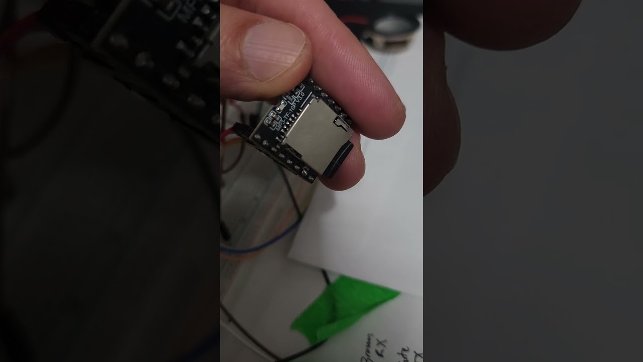
Hi, just message the seller. Should not be a problem.
Hi guys,
I’m currently using this device to display an arrow in the direction of a float value received from the RX pin of the dev board. I’m unsure of which GPIO is meant to be attached to the RX and TX pins, as I tested “GPIO20 RX, and GPIO21 TX” which was previously mentioned by OP and didn’t receive any data. Is anyone able to check this for themselves? I couldn’t find it in the documentation either.
I have also been trying to use gpio 20 & 21 with no luck (i am connecting a mp3 player). From my understanding these are UARTO and used for the usb/serial monitoring.
I unplugged the usb after uploading software, I connected power/ground separately separately, disabled usb CDC on boot and still no communication over these pins.
Gpio3 is available and accessible via the adapter board but i need two pins. Gpio10 is also available but not accessible on the adapter board so i would need to solder directly to the C3 board. Trying to avoid this.
Anybody had luck with rx/tx communications over GPIO 20/21?
Hello, I was able to successfully connect via gpio pins 20 and 21 (tx1 and rx1 on the adapter board) and send and recieve communications. They are UART0. U need to enable USB CDC in arduino settings.
Your attached device needs to be powered on AFTER the knob boots up.
This is because the boot ROM momentarily uses UART0 for debug until USB CDC fully takes over. That can glitch your accessory’s RX during boot.
Can you post your code please?
CODE, PLEASE! Post the YAML file.
code would be epic if available please… I am trying to rotate between buttons as a menu but I am failing LOL
I just picked up the same 2.1" model, has anyone been able to get ESPHome on it yet?
