Hi Ben,
have you measured the contacts from ESP to the Shift registers?
What was the outcome?
Still waiting for my board to arrive. 
Hi Ben,
have you measured the contacts from ESP to the Shift registers?
What was the outcome?
Still waiting for my board to arrive.
Hi everyone, I have also bought this PCB and I can’t get it to work either.
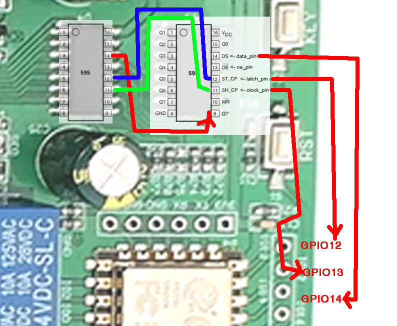
So far I have figured out that this continuity with a 0.00 resistance multimeter between the pins
(GPIO12 to ST_CP)
(GIPO13 to SH_CP)
(GPIO14 to DS)
but without any results I have not managed to get it to work. (Sorry for my bad English)
The good news is, it’s by the same manufacturer LC Tech who design and manufacture the very common four-channel and eight-channel ESP-12F relay boards. That’s their logo in the bottom left corner of the printed circuit board, near the two-position connector.
Their web page shows this contact e-mail address:
E-mail:[email protected]/[email protected]
I have previously requested assistance, and they were very helpful. In my case it was an eight-channel ESP-12F relay board. In case it might be helpful, these were the GPIO assignments on their eight-channel relay board:
#
# Eight GPIO relay outputs,
# exposed as switches in Home Assistant,
# one for each lighting zone
#
switch:
  - platform: gpio
    pin: GPIO16
    name: Zone1
    id: relay1
    restore_mode: always_off

  - platform: gpio
    pin: GPIO14
    name: Zone2
    id: relay2
    restore_mode: always_off

  - platform: gpio
    pin: GPIO12
    name: Zone3
    id: relay3
    restore_mode: always_off

  - platform: gpio
    pin: GPIO13
    name: Zone4
    id: relay4
    restore_mode: always_off

  - platform: gpio
    pin: GPIO15
    name: Zone5
    id: relay5
    restore_mode: always_off

  - platform: gpio
    pin: GPIO0
    name: Zone6
    id: relay6
    restore_mode: always_off

  - platform: gpio
    pin: GPIO4
    name: Zone7
    id: relay7
    restore_mode: always_off

  - platform: gpio
    pin: GPIO5
    name: Zone8
    id: relay8
    restore_mode: always_off
Thanks Keith for the contribution, the eight relay board works directly on the esp12f gpios and the 16 relay board works with two 74hc595 that communicate directly with the esp12f through three pins, the dilemma is to find the correct communication to be able to control The relay’s, the 74hc595 I have seen that it is usually used for the 3d led cubes that was used with arduino.
In my opinion to control 16 relay’s with an esp12f it would be more correct with an i2c communication, I have found a board on ebay that uses this communication to move 16 relay’s but it made me a expensive of money.
This is the code that I have used, in HA it recognizes it but does not move the relays
# Example configuration entry
sn74hc595:
  - id: 'sn74hc595_hub'
    data_pin: GPIO14
    clock_pin: GPIO13
    latch_pin: GPIO12
#    oe_pin: D6
    sr_count: 1

# Individual outputs
switch:
  - platform: gpio
    name: "SN74HC595 Pin #0"
    pin:
      sn74hc595: sn74hc595_hub
      # Use pin number 0
      number: 0
      inverted: false
  - platform: gpio
    name: "SN74HC595 Pin #1"
    pin:
      sn74hc595: sn74hc595_hub
      # Use pin number 1
      number: 1
      inverted: false
  - platform: gpio
    name: "SN74HC595 Pin #2"
    pin:
      sn74hc595: sn74hc595_hub
      # Use pin number 2
      number: 2
      inverted: false
  - platform: gpio
    name: "SN74HC595 Pin #3"
    pin:
      sn74hc595: sn74hc595_hub
      # Use pin number 3
      number: 3
      inverted: false
  - platform: gpio
    name: "SN74HC595 Pin #4"
    pin:
      sn74hc595: sn74hc595_hub
      # Use pin number 4
      number: 4
      inverted: false
  - platform: gpio
    name: "SN74HC595 Pin #5"
    pin:
      sn74hc595: sn74hc595_hub
      # Use pin number 5
      number: 5
      inverted: false
  - platform: gpio
    name: "SN74HC595 Pin #6"
    pin:
      sn74hc595: sn74hc595_hub
      # Use pin number 6
      number: 6
      inverted: false
  - platform: gpio
    name: "SN74HC595 Pin #7"
    pin:
      sn74hc595: sn74hc595_hub
      # Use pin number 7
      number: 7
      inverted: false
  - platform: gpio
    name: "SN74HC595 Pin #8"
    pin:
      sn74hc595: sn74hc595_hub
      # Use pin number 8
      number: 8
      inverted: false
  - platform: gpio
    name: "SN74HC595 Pin #9"
    pin:
      sn74hc595: sn74hc595_hub
      # Use pin number 9
      number: 9
      inverted: false
  - platform: gpio
    name: "SN74HC595 Pin #10"
    pin:
      sn74hc595: sn74hc595_hub
      # Use pin number 10
      number: 10
      inverted: false
  - platform: gpio
    name: "SN74HC595 Pin #11"
    pin:
      sn74hc595: sn74hc595_hub
      # Use pin number 11
      number: 11
      inverted: false
  - platform: gpio
    name: "SN74HC595 Pin #12"
    pin:
      sn74hc595: sn74hc595_hub
      # Use pin number 12
      number: 12
      inverted: false
  - platform: gpio
    name: "SN74HC595 Pin #13"
    pin:
      sn74hc595: sn74hc595_hub
      # Use pin number 13
      number: 13
      inverted: false
  - platform: gpio
    name: "SN74HC595 Pin #14"
    pin:
      sn74hc595: sn74hc595_hub
      # Use pin number 14
      number: 14
      inverted: false
  - platform: gpio
    name: "SN74HC595 Pin #15"
    pin:
      sn74hc595: sn74hc595_hub
      # Use pin number 15
      number: 15
      inverted: false
  - platform: gpio
    name: "SN74HC595 Pin #16"
    pin:
      sn74hc595: sn74hc595_hub
      # Use pin number 16
      number: 16
      inverted: false
I have been looking for more information about this plate and after much searching I have found in a Chinese blog this information that is quite similar to this plate, to see if someone can decipher and understand it.
https://blog.csdn.net/weixin_43796593/article/details/84639021
(sorry for my bad English)
I just received mine.
I measured the board and I come to the conclusion that U4 is connected to the I/Os not U5.
Nevertheless:
Can you try this config once:
sn74hc595:
  - id: 'sn74hc595_hub'
    data_pin: GPIO14
    clock_pin: GPIO13
    latch_pin: GPIO12
    oe_pin: GPIO05
    sr_count: 2
THis is indead what I have measured on the board.
I will test mine later on, I have currently not much time left.
Congratulations Chirstian, with this code that you have sent everything worked perfectly, thank you very much 

Thats nice @juanjovi
For me only the LED on the Relay switches on, but the Relay is still not switching.
Have you measured the function of the relay?
Thanks and BR
Christian
And I found my issue…
When bying a 24V Version, you should supply 24V and not 12V.
With 12V the relays are not working…
For completenes, hereby the code which is working.
esphome:
name: coverlivingroom
esp8266:
board: esp01_1m
wifi:
reboot_timeout: 0s
domain: ".my.secret.domain"
networks:
- ssid: !secret wifi_ssid
- password: !secret wifi_pass
- ssid: 'rescue'
- password: '12345678'
#use_address: ''
# Enable logging
logger:
# Enable Web server
web_server:
port: 80
# Enable Home Assistant API/OTA
api:
password: !secret api_pass2
reboot_timeout: 0s
ota:
safe_mode: true
password: !secret ota_pass
# Sync time with Home Assistant
time:
- platform: homeassistant
id: homeassistant_time
# Example configuration entry
sn74hc595:
  - id: 'sn74hc595_hub'
    data_pin: GPIO14
    clock_pin: GPIO13
    latch_pin: GPIO12
    oe_pin: GPIO05
    sr_count: 2
# Individual outputs
switch:
- platform: gpio
name: "SN74HC595 Pin #0"
pin:
sn74hc595: sn74hc595_hub
# Use pin number 0
number: 0
inverted: false
- platform: gpio
name: "SN74HC595 Pin #1"
pin:
sn74hc595: sn74hc595_hub
# Use pin number 1
number: 1
inverted: false
- platform: gpio
name: "SN74HC595 Pin #2"
pin:
sn74hc595: sn74hc595_hub
# Use pin number 2
number: 2
inverted: false
- platform: gpio
name: "SN74HC595 Pin #3"
pin:
sn74hc595: sn74hc595_hub
# Use pin number 3
number: 3
inverted: false
- platform: gpio
name: "SN74HC595 Pin #4"
pin:
sn74hc595: sn74hc595_hub
# Use pin number 4
number: 4
inverted: false
- platform: gpio
name: "SN74HC595 Pin #5"
pin:
sn74hc595: sn74hc595_hub
# Use pin number 5
number: 5
inverted: false
- platform: gpio
name: "SN74HC595 Pin #6"
pin:
sn74hc595: sn74hc595_hub
# Use pin number 6
number: 6
inverted: false
- platform: gpio
name: "SN74HC595 Pin #7"
pin:
sn74hc595: sn74hc595_hub
# Use pin number 7
number: 7
inverted: false
- platform: gpio
name: "SN74HC595 Pin #8"
pin:
sn74hc595: sn74hc595_hub
# Use pin number 8
number: 8
inverted: false
- platform: gpio
name: "SN74HC595 Pin #9"
pin:
sn74hc595: sn74hc595_hub
# Use pin number 9
number: 9
inverted: false
- platform: gpio
name: "SN74HC595 Pin #10"
pin:
sn74hc595: sn74hc595_hub
# Use pin number 10
number: 10
inverted: false
- platform: gpio
name: "SN74HC595 Pin #11"
pin:
sn74hc595: sn74hc595_hub
# Use pin number 11
number: 11
inverted: false
- platform: gpio
name: "SN74HC595 Pin #12"
pin:
sn74hc595: sn74hc595_hub
# Use pin number 12
number: 12
inverted: false
- platform: gpio
name: "SN74HC595 Pin #13"
pin:
sn74hc595: sn74hc595_hub
# Use pin number 13
number: 13
inverted: false
- platform: gpio
name: "SN74HC595 Pin #14"
pin:
sn74hc595: sn74hc595_hub
# Use pin number 14
number: 14
inverted: false
- platform: gpio
name: "SN74HC595 Pin #15"
pin:
sn74hc595: sn74hc595_hub
# Use pin number 15
number: 15
inverted: false
And for everyone who plans to use this board as “time-based-cover”, my v1 config:
substitutions:
#Substitutions added for easy maintenance
  device_name: living16xrelay
  cover_kitchen: coverkitchen
  cover_kitchen_open_duration: 16.05sec
  cover_kitchen_close_duration: 15.00sec
  cover_island: coverisland
  cover_island_open_duration: 16.05sec
  cover_island_close_duration: 15.00sec
  cover_diner: coverdiner
  cover_diner_open_duration: 16.05sec
  cover_diner_close_duration: 15.00sec
  cover_living: coverliving
  cover_living_open_duration: 16.05sec
  cover_living_close_duration: 15.00sec
  cover_bath: coverbath
  cover_bath_open_duration: 16.05sec
  cover_bath_close_duration: 15.00sec


esphome:
  name: ${device_name}

esp8266:
  board: esp01_1m

<<: !include templates/templatesensorsv1.yaml

wifi:
  reboot_timeout: 0s
  domain: ".my.secret.domain"
  networks:
  - ssid: !secret wifi_ssid
  - password: !secret wifi_pass
  - ssid: 'rescue'
  - password: '12345678'
  #use_address: 'coverlivingroom.my.secret.domain'

# Enable logging
logger:

  # Enable Web server
web_server:
  port: 80

# Enable Home Assistant API/OTA
api:
  password: !secret api_pass2
  reboot_timeout: 0s
ota:
  safe_mode: true
  password: !secret ota_pass

# Sync time with Home Assistant
time:
  - platform: homeassistant
    id: homeassistant_time

# Intiate Shift Register GPIOs
sn74hc595:
  - id: "sn74hc595_hub"
    data_pin: GPIO14
    clock_pin: GPIO13
    latch_pin: GPIO12
    oe_pin: GPIO05
    sr_count: 2


switch:

# Switch to restart the shutter
  - platform: restart
    id: reset
    name: "${device_name} Restart"

#Relay by ShiftRegister (id only, so only internal)
#Even if not required, in case motors are correctly wired, adding interlock to always make sure only 1 Relay is driving, especially in Web Server
  - platform: gpio
    id: relay_kitchen_up
    interlock: &interlock_group0 [relay_kitchen_up, relay_kitchen_down]
    restore_mode: always off
    pin:
      sn74hc595: sn74hc595_hub
      # Use pin number 0
      number: 0
      inverted: false

  - platform: gpio
    id: relay_kitchen_down
    interlock: *interlock_group0
    restore_mode: always off
    pin:
      sn74hc595: sn74hc595_hub
      # Use pin number 1
      number: 1
      inverted: false

  - platform: gpio
    id: relay_island_up
    interlock: &interlock_group1 [relay_island_up, relay_island_down]
    restore_mode: always off
    pin:
      sn74hc595: sn74hc595_hub
      # Use pin number 2
      number: 2
      inverted: false

  - platform: gpio
    id: relay_island_down
    interlock: *interlock_group1
    restore_mode: always off
    pin:
      sn74hc595: sn74hc595_hub
      # Use pin number 3
      number: 3
      inverted: false

  - platform: gpio
    id: relay_diner_up
    interlock: &interlock_group3 [relay_diner_up, relay_diner_down]
    restore_mode: always off
    pin:
      sn74hc595: sn74hc595_hub
      # Use pin number 4
      number: 4
      inverted: false

  - platform: gpio
    id: relay_diner_down
    interlock: *interlock_group3
    restore_mode: always off
    pin:
      sn74hc595: sn74hc595_hub
      # Use pin number 5
      number: 5
      inverted: false

  - platform: gpio
    id: relay_living_up
    interlock: &interlock_group4 [relay_living_up, relay_living_down]
    restore_mode: always off
    pin:
      sn74hc595: sn74hc595_hub
      # Use pin number 6
      number: 6
      inverted: false

  - platform: gpio
    id: relay_living_down
    interlock: *interlock_group4
    restore_mode: always off
    pin:
      sn74hc595: sn74hc595_hub
      # Use pin number 7
      number: 7
      inverted: false

  - platform: gpio
    id: relay_bath_up
    interlock: &interlock_group5 [relay_bath_up, relay_bath_down]
    restore_mode: always off
    pin:
      sn74hc595: sn74hc595_hub
      # Use pin number 8
      number: 8
      inverted: false

  - platform: gpio
    id: relay_bath_down
    interlock: *interlock_group5
    restore_mode: always off
    pin:
      sn74hc595: sn74hc595_hub
      # Use pin number 9
      number: 9
      inverted: false

  - platform: gpio
    id: no_use10
    restore_mode: always off
    pin:
      sn74hc595: sn74hc595_hub
      # Use pin number 10
      number: 10
      inverted: false
  - platform: gpio
    id: no_use11
    pin:
      sn74hc595: sn74hc595_hub
      # Use pin number 11
      number: 11
      inverted: false
  - platform: gpio
    id: no_use12
    restore_mode: always off
    pin:
      sn74hc595: sn74hc595_hub
      # Use pin number 12
      number: 12
      inverted: false
  - platform: gpio
    id: no_use13
    restore_mode: always off
    pin:
      sn74hc595: sn74hc595_hub
      # Use pin number 13
      number: 13
      inverted: false
  - platform: gpio
    id: no_use14
    restore_mode: always off
    pin:
      sn74hc595: sn74hc595_hub
      # Use pin number 14
      number: 14
      inverted: false
  - platform: gpio
    id: no_use15
    restore_mode: always off
    pin:
      sn74hc595: sn74hc595_hub
      # Use pin number 15
      number: 15
      inverted: false

cover:
- platform: time_based
  name: "${cover_kitchen}"
  id: cover_kitchen
  open_action:
    - switch.turn_on: relay_kitchen_up
  open_duration: ${cover_kitchen_open_duration}
  close_action:
    - switch.turn_on: relay_kitchen_down
  close_duration: ${cover_kitchen_close_duration}
  stop_action:
    - switch.turn_off: relay_kitchen_up
    - switch.turn_off: relay_kitchen_down

- platform: time_based
  name: "${cover_island}"
  id: cover_island
  open_action:
    - switch.turn_on: relay_island_up
  open_duration: ${cover_island_open_duration}
  close_action:
    - switch.turn_on: relay_island_down
  close_duration: ${cover_island_close_duration}
  stop_action:
    - switch.turn_off: relay_island_up
    - switch.turn_off: relay_island_down


- platform: time_based
  name: "${cover_diner}"
  id: cover_diner
  open_action:
    - switch.turn_on: relay_diner_up
  open_duration: ${cover_diner_open_duration}
  close_action:
    - switch.turn_on: relay_diner_down
  close_duration: ${cover_diner_close_duration}
  stop_action:
    - switch.turn_off: relay_diner_up
    - switch.turn_off: relay_diner_down

- platform: time_based
  name: "${cover_living}"
  id: cover_living
  open_action:
    - switch.turn_on: relay_living_up
  open_duration: ${cover_living_open_duration}
  close_action:
    - switch.turn_on: relay_living_down
  close_duration: ${cover_living_close_duration}
  stop_action:
    - switch.turn_off: relay_living_up
    - switch.turn_off: relay_living_down

- platform: time_based
  name: "${cover_bath}"
  id: cover_bath
  open_action:
    - switch.turn_on: relay_bath_up
  open_duration: ${cover_bath_open_duration}
  close_action:
    - switch.turn_on: relay_bath_down
  close_duration: ${cover_bath_close_duration}
  stop_action:
    - switch.turn_off: relay_bath_up
    - switch.turn_off: relay_bath_down
The wiring, I recommend to do it like that:

This enables you to forget about interlock_wait_time, as it can never power both ends of your motor.
Thanks to @alfredopironti (Github Time-Based Cover - calculate interlock_wait_time to open/close duration + add max_duration #778
…send Line (220V) to the COM of relay_1, use NO of relay_1 for cover direction UP, join NC of relay_1 with NO of relay_2; use COM of relay_2 for cover direction DOWN. This makes programming straightforward as you get one relay per direction, and electrical interlock (but, again, no interlock_wait_time!)…
Happy ESP-ing 
Awesome work! Can this be adapted to turn on 16 valves?
Sure!
If fitting to the relay, no issue.
Just connect your power to the relay and configure ESPhome to your needs.
e.g. Sprinkler system, some example also here:
Sprinkler
Awesome! Thx. Now I can compare mine to that code see how to use ESPHome as this is a nice complicated setup.
Thx again 
any one was able to use al 16 relays?
Yes.
All tested and working.
Hello All,
I’ve got the same board with 16 relays.
Can anyone please share the source code for the demo sample (Arduino code)?
Thank you.
Hello smart people,
I have purchased a couple of these boards, and was hoping based on the above discussion if someone knows how to adapt this to address the relays directly when uploading a sketch, so something like:
int latchPin = 12;  // Latch pin of 74HC595 is connected to Digital pin 5
int clockPin = 13; // Clock pin of 74HC595 is connected to Digital pin 6
int dataPin = 14;  // Data pin of 74HC595 is connected to Digital pin 4

void setup()
{
  // Set all the pins of 74HC595 as OUTPUT
  pinMode(latchPin, OUTPUT);
  pinMode(dataPin, OUTPUT);
  pinMode(clockPin, OUTPUT);
My problem is, if these 3 pins are the ones to use to address the 74HC595’s then how would you go about sending the data to trigger the LED/RELAY for each of the 16 relays, I’m just a bit out of my depth here and there is no doco and I am awaiting responses from LC Tech in china.
Do I need to care about the OE pin ? Tried to gain some better understanding from this article: In-Depth: How 74HC595 Shift Register Works & Interface with Arduino
But yeah wondering if anyone had any ideas on how to actually control the LED’s/RELAYS on these 16 relay boards when you flash the code it comes shipped with.
Does anyone have example code or the code with which these units are shipped so I could reverse engineer ? The code provided in some of the listings doesn’t seem to do anything I think it is for the lower count relay boards that do direct pinout to relay: DC 5V/12V/24V ESP8266 WIFI 16 Channels Relay Module ESP-12F Development Board | eBay
I know this is more of a HOME automation site, but its the only place I have found a conversation about this board and the code to control it.
I have some code that sort of works on this board (short pin IO0 to GND to put in flash mode)
If anyone knows what the data format you need to feed the 74HC595 I would be eternally grateful, I am just trying stuff but its not particularly reliable (different results dependant on data order sent, makes me think sending too much data and there is overflow from one request to the next).
This version seems to activate Relay 9 (not sure how), then it jump switches between relay 8 and 16.
// LCTech 16ch Relay board with 2x74HC595 shift registers - replicates close to out of box relay testing function
int latchPin = 12;  // Latch pin of 74HC595 is connected to Digital pin 5
int clockPin = 13; // Clock pin of 74HC595 is connected to Digital pin 6
int dataPin = 14;  // Data pin of 74HC595 is connected to Digital pin 4
int oePin = 5;    // oePin - not using this

void setup()
{
  // Set all the pins of 74HC595 as OUTPUT
  pinMode(latchPin, OUTPUT);
  pinMode(dataPin, OUTPUT);
  pinMode(clockPin, OUTPUT);
  pinMode(oePin, OUTPUT);

  // Setup serial comms
  Serial.begin(115200);
}

void loop()
{

      Serial.println("Relay #16 = 0b0000");
      digitalWrite(latchPin, LOW);
      shiftOut(dataPin, clockPin, LSBFIRST, 0b0000);
      digitalWrite(latchPin, HIGH);
      delay(3000);

      Serial.println("Relay #8 = 0b0001");
      digitalWrite(latchPin, LOW);
      shiftOut(dataPin, clockPin, LSBFIRST, 0b0001);
      digitalWrite(latchPin, HIGH);
      delay(3000);

}
I contacted the manufacture as well, no answer received.
You could check the source code of the component in ESPhome and you would have some indications how to port to arduino.
Hello
I have found out how to control it using Arduino I will create a sample code with a function that takes the relay number and state as a parameter and chang the state.
I will be posting it later today.