16xRelay with ESP12F Onboard and two Shift Register (74HC595)

Hi guys,

I am planning to control my roller shutters with a Relay board.
And there I have seen this board: Aliexpress - ESP8266 WIFI 16 Channel Relay Module ESP-12F

I have neither received the board yet or able to download the sample file, which is mentioned.

So far as I understood, I need to define the data_pin, clock_pin and latch_pin where the ESP is connected to.
See here:
SN74HC595 I/O Expander

Anyone, any idea how I can figure that out?

Thanks in advance!

Cheers

1 Like

Hi Harry,
Thanks a lot for your answer.

You wanted to do the exact same thing means also you used that board or you developed your own circuit?

And sure, any help is highly appreciated :slight_smile:

Sorry, I didn’t check the links on your post.
What I wanted to do was control 22 relays with a single esp32 chip. So I used an sn74… Extender thingy to get the extra gpios.

So the idea was 1 esp32 with six separate 4relay boards not the one you linked… (total 24 relays)

This didn’t work very well, as, perhaps due to wrong cabling, I had some weird behaviors (pins going on when they shouldn’t and everything switching on during esp boot time).

Anyway, I ended up connecting the 6 relay boards to two separate esp chips directly which works fine.

The only issue I have is that the esp’s sometimes reboot when I shut off all the relays simultaneously and I cannot figure out why so far…

Just my 2¢ :slight_smile:

Well just follow esphome doc that you indicated ! What is your problem there ?

The ESPHome Doc is fine, no question on that :slight_smile:

But the board I ordered does have the ESP already connected to the Shift Register… But on which ports is not clear to me.
If I don’t know the GPIOs, I don’t know what to put in my ESPHome yaml, right?

So, I am asking, is someone having a brilliant idea? Or just measuring with a multimeter?

1 Like

Well sorry to say but you took the problem in the wrong way !! You first identify how product you want to use works before buying it or you expose yourself at some big disappointments from time to time !
There is no miracle here ! If you can’t find the info from manufacturer/internet you’ll have to track the routing on the printed board to determine how ESP is wired :wink:
Did u try to contact seller on Ali ?

Hi Vincén,

Yes I have contacted the seller, but I am not sure if I get what I want :wink:
At least he replied to check with the producer.
In the describtion an example code is mentioned as well, so I hope I get this and can see the assigned ports in Arduino code.

And if nothings helps, yeah, I have to check the routing obviously.

Crossing fingers that it works like it should.
In any case I get back here, reporting what happened with the board and if it works like intended for my roller shutters :wink:

warm regards

Good luck with it but it should be ok as design looks very basic :wink:

Tanks a lot.
And Yes I agree, should not be too hard to achieve.
Hopefully there are some pull down resistors and not only the connection to the shift register:D

I have the same board and also cannot get it working. If you get a sample program can you please post. Cheers

Hi Ben,

have you measured the contacts from ESP to the Shift registers?
What was the outcome?

Still waiting for my board to arrive. :frowning:

Hi everyone, I have also bought this PCB and I can’t get it to work either.
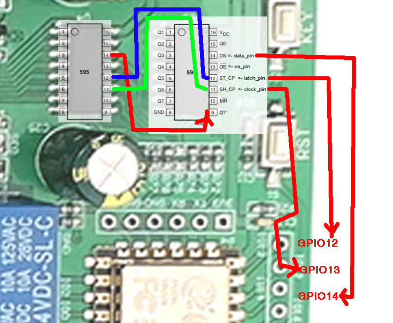
So far I have figured out that this continuity with a 0.00 resistance multimeter between the pins
(GPIO12 to ST_CP)
(GIPO13 to SH_CP)
(GPIO14 to DS)
but without any results I have not managed to get it to work. (Sorry for my bad English)

1 Like

The good news is, it’s by the same manufacturer LC Tech who design and manufacture the very common four-channel and eight-channel ESP-12F relay boards. That’s their logo in the bottom left corner of the printed circuit board, near the two-position connector.

Their web page shows this contact e-mail address:
E-mail:[email protected]/[email protected]

I have previously requested assistance, and they were very helpful. In my case it was an eight-channel ESP-12F relay board. In case it might be helpful, these were the GPIO assignments on their eight-channel relay board:

#
# Eight GPIO relay outputs, 
# exposed as switches in Home Assistant,
# one for each lighting zone
#
switch:
  - platform: gpio
    pin: GPIO16
    name: Zone1
    id: relay1
    restore_mode: always_off
    
  - platform: gpio
    pin: GPIO14
    name: Zone2
    id: relay2
    restore_mode: always_off
    
  - platform: gpio
    pin: GPIO12
    name: Zone3
    id: relay3
    restore_mode: always_off
    
  - platform: gpio
    pin: GPIO13
    name: Zone4
    id: relay4
    restore_mode: always_off

  - platform: gpio
    pin: GPIO15
    name: Zone5
    id: relay5
    restore_mode: always_off
    
  - platform: gpio
    pin: GPIO0
    name: Zone6
    id: relay6
    restore_mode: always_off
    
  - platform: gpio
    pin: GPIO4
    name: Zone7
    id: relay7
    restore_mode: always_off
    
  - platform: gpio
    pin: GPIO5
    name: Zone8
    id: relay8
    restore_mode: always_off

Thanks Keith for the contribution, the eight relay board works directly on the esp12f gpios and the 16 relay board works with two 74hc595 that communicate directly with the esp12f through three pins, the dilemma is to find the correct communication to be able to control The relay’s, the 74hc595 I have seen that it is usually used for the 3d led cubes that was used with arduino.
In my opinion to control 16 relay’s with an esp12f it would be more correct with an i2c communication, I have found a board on ebay that uses this communication to move 16 relay’s but it made me a expensive of money.

This is the code that I have used, in HA it recognizes it but does not move the relays

# Example configuration entry
sn74hc595:
  - id: 'sn74hc595_hub'
    data_pin: GPIO14
    clock_pin: GPIO13
    latch_pin: GPIO12
#    oe_pin: D6
    sr_count: 1

# Individual outputs
switch:
  - platform: gpio
    name: "SN74HC595 Pin #0"
    pin:
      sn74hc595: sn74hc595_hub
      # Use pin number 0
      number: 0
      inverted: false
  - platform: gpio
    name: "SN74HC595 Pin #1"
    pin:
      sn74hc595: sn74hc595_hub
      # Use pin number 1
      number: 1
      inverted: false
  - platform: gpio
    name: "SN74HC595 Pin #2"
    pin:
      sn74hc595: sn74hc595_hub
      # Use pin number 2
      number: 2
      inverted: false
  - platform: gpio
    name: "SN74HC595 Pin #3"
    pin:
      sn74hc595: sn74hc595_hub
      # Use pin number 3
      number: 3
      inverted: false
  - platform: gpio
    name: "SN74HC595 Pin #4"
    pin:
      sn74hc595: sn74hc595_hub
      # Use pin number 4
      number: 4
      inverted: false
  - platform: gpio
    name: "SN74HC595 Pin #5"
    pin:
      sn74hc595: sn74hc595_hub
      # Use pin number 5
      number: 5
      inverted: false
  - platform: gpio
    name: "SN74HC595 Pin #6"
    pin:
      sn74hc595: sn74hc595_hub
      # Use pin number 6
      number: 6
      inverted: false
  - platform: gpio
    name: "SN74HC595 Pin #7"
    pin:
      sn74hc595: sn74hc595_hub
      # Use pin number 7
      number: 7
      inverted: false
  - platform: gpio
    name: "SN74HC595 Pin #8"
    pin:
      sn74hc595: sn74hc595_hub
      # Use pin number 8
      number: 8
      inverted: false
  - platform: gpio
    name: "SN74HC595 Pin #9"
    pin:
      sn74hc595: sn74hc595_hub
      # Use pin number 9
      number: 9
      inverted: false
  - platform: gpio
    name: "SN74HC595 Pin #10"
    pin:
      sn74hc595: sn74hc595_hub
      # Use pin number 10
      number: 10
      inverted: false
  - platform: gpio
    name: "SN74HC595 Pin #11"
    pin:
      sn74hc595: sn74hc595_hub
      # Use pin number 11
      number: 11
      inverted: false
  - platform: gpio
    name: "SN74HC595 Pin #12"
    pin:
      sn74hc595: sn74hc595_hub
      # Use pin number 12
      number: 12
      inverted: false
  - platform: gpio
    name: "SN74HC595 Pin #13"
    pin:
      sn74hc595: sn74hc595_hub
      # Use pin number 13
      number: 13
      inverted: false
  - platform: gpio
    name: "SN74HC595 Pin #14"
    pin:
      sn74hc595: sn74hc595_hub
      # Use pin number 14
      number: 14
      inverted: false
  - platform: gpio
    name: "SN74HC595 Pin #15"
    pin:
      sn74hc595: sn74hc595_hub
      # Use pin number 15
      number: 15
      inverted: false
  - platform: gpio
    name: "SN74HC595 Pin #16"
    pin:
      sn74hc595: sn74hc595_hub
      # Use pin number 16
      number: 16
      inverted: false

I have been looking for more information about this plate and after much searching I have found in a Chinese blog this information that is quite similar to this plate, to see if someone can decipher and understand it.
https://blog.csdn.net/weixin_43796593/article/details/84639021
(sorry for my bad English)

I just received mine.
I measured the board and I come to the conclusion that U4 is connected to the I/Os not U5.

Nevertheless:
Can you try this config once:

sn74hc595:
  - id: 'sn74hc595_hub'
    data_pin: GPIO14
    clock_pin: GPIO13
    latch_pin: GPIO12
    oe_pin: GPIO05
    sr_count: 2

THis is indead what I have measured on the board.

I will test mine later on, I have currently not much time left.

1 Like

BTW: Yes right this China LC
ESP12F 16x Relay

1 Like

Congratulations Chirstian, with this code that you have sent everything worked perfectly, thank you very much :+1: :clap: :clap: :clap:

Thats nice @juanjovi
For me only the LED on the Relay switches on, but the Relay is still not switching.

Have you measured the function of the relay?

Thanks and BR
Christian

1 Like

And I found my issue…
When bying a 24V Version, you should supply 24V and not 12V.
With 12V the relays are not working…

For completenes, hereby the code which is working.

esphome:
  name: coverlivingroom

esp8266:
  board: esp01_1m

wifi:
  reboot_timeout: 0s
  domain: ".my.secret.domain"
  networks:
  - ssid: !secret wifi_ssid
  - password: !secret wifi_pass
  - ssid: 'rescue'
  - password: '12345678'
  #use_address: ''

# Enable logging
logger:

  # Enable Web server
web_server:
  port: 80

# Enable Home Assistant API/OTA
api:
  password: !secret api_pass2
  reboot_timeout: 0s
ota:
  safe_mode: true
  password: !secret ota_pass

# Sync time with Home Assistant
time:
  - platform: homeassistant
    id: homeassistant_time

# Example configuration entry
sn74hc595:
  - id: 'sn74hc595_hub'
    data_pin: GPIO14
    clock_pin: GPIO13
    latch_pin: GPIO12
    oe_pin: GPIO05
    sr_count: 2

# Individual outputs
switch:
  - platform: gpio
    name: "SN74HC595 Pin #0"
    pin:
      sn74hc595: sn74hc595_hub
      # Use pin number 0
      number: 0
      inverted: false
  - platform: gpio
    name: "SN74HC595 Pin #1"
    pin:
      sn74hc595: sn74hc595_hub
      # Use pin number 1
      number: 1
      inverted: false
  - platform: gpio
    name: "SN74HC595 Pin #2"
    pin:
      sn74hc595: sn74hc595_hub
      # Use pin number 2
      number: 2
      inverted: false
  - platform: gpio
    name: "SN74HC595 Pin #3"
    pin:
      sn74hc595: sn74hc595_hub
      # Use pin number 3
      number: 3
      inverted: false
  - platform: gpio
    name: "SN74HC595 Pin #4"
    pin:
      sn74hc595: sn74hc595_hub
      # Use pin number 4
      number: 4
      inverted: false
  - platform: gpio
    name: "SN74HC595 Pin #5"
    pin:
      sn74hc595: sn74hc595_hub
      # Use pin number 5
      number: 5
      inverted: false
  - platform: gpio
    name: "SN74HC595 Pin #6"
    pin:
      sn74hc595: sn74hc595_hub
      # Use pin number 6
      number: 6
      inverted: false
  - platform: gpio
    name: "SN74HC595 Pin #7"
    pin:
      sn74hc595: sn74hc595_hub
      # Use pin number 7
      number: 7
      inverted: false
  - platform: gpio
    name: "SN74HC595 Pin #8"
    pin:
      sn74hc595: sn74hc595_hub
      # Use pin number 8
      number: 8
      inverted: false
  - platform: gpio
    name: "SN74HC595 Pin #9"
    pin:
      sn74hc595: sn74hc595_hub
      # Use pin number 9
      number: 9
      inverted: false
  - platform: gpio
    name: "SN74HC595 Pin #10"
    pin:
      sn74hc595: sn74hc595_hub
      # Use pin number 10
      number: 10
      inverted: false
  - platform: gpio
    name: "SN74HC595 Pin #11"
    pin:
      sn74hc595: sn74hc595_hub
      # Use pin number 11
      number: 11
      inverted: false
  - platform: gpio
    name: "SN74HC595 Pin #12"
    pin:
      sn74hc595: sn74hc595_hub
      # Use pin number 12
      number: 12
      inverted: false
  - platform: gpio
    name: "SN74HC595 Pin #13"
    pin:
      sn74hc595: sn74hc595_hub
      # Use pin number 13
      number: 13
      inverted: false
  - platform: gpio
    name: "SN74HC595 Pin #14"
    pin:
      sn74hc595: sn74hc595_hub
      # Use pin number 14
      number: 14
      inverted: false
  - platform: gpio
    name: "SN74HC595 Pin #15"
    pin:
      sn74hc595: sn74hc595_hub
      # Use pin number 15
      number: 15
      inverted: false

And for everyone who plans to use this board as “time-based-cover”, my v1 config:

substitutions:
#Substitutions added for easy maintenance
  device_name: living16xrelay
  cover_kitchen: coverkitchen
  cover_kitchen_open_duration: 16.05sec
  cover_kitchen_close_duration: 15.00sec
  cover_island: coverisland
  cover_island_open_duration: 16.05sec
  cover_island_close_duration: 15.00sec
  cover_diner: coverdiner
  cover_diner_open_duration: 16.05sec
  cover_diner_close_duration: 15.00sec
  cover_living: coverliving
  cover_living_open_duration: 16.05sec
  cover_living_close_duration: 15.00sec
  cover_bath: coverbath
  cover_bath_open_duration: 16.05sec
  cover_bath_close_duration: 15.00sec
  
  
esphome:
  name: ${device_name}

esp8266:
  board: esp01_1m

<<: !include templates/templatesensorsv1.yaml

wifi:
  reboot_timeout: 0s
  domain: ".my.secret.domain"
  networks:
  - ssid: !secret wifi_ssid
  - password: !secret wifi_pass
  - ssid: 'rescue'
  - password: '12345678'
  #use_address: 'coverlivingroom.my.secret.domain'

# Enable logging
logger:

  # Enable Web server
web_server:
  port: 80

# Enable Home Assistant API/OTA
api:
  password: !secret api_pass2
  reboot_timeout: 0s
ota:
  safe_mode: true
  password: !secret ota_pass

# Sync time with Home Assistant
time:
  - platform: homeassistant
    id: homeassistant_time

# Intiate Shift Register GPIOs
sn74hc595:
  - id: "sn74hc595_hub"
    data_pin: GPIO14
    clock_pin: GPIO13
    latch_pin: GPIO12
    oe_pin: GPIO05
    sr_count: 2


switch:

# Switch to restart the shutter
  - platform: restart
    id: reset
    name: "${device_name} Restart"

#Relay by ShiftRegister (id only, so only internal)
#Even if not required, in case motors are correctly wired, adding interlock to always make sure only 1 Relay is driving, especially in Web Server
  - platform: gpio
    id: relay_kitchen_up
    interlock: &interlock_group0 [relay_kitchen_up, relay_kitchen_down]
    restore_mode: always off
    pin:
      sn74hc595: sn74hc595_hub
      # Use pin number 0
      number: 0
      inverted: false
  
  - platform: gpio
    id: relay_kitchen_down
    interlock: *interlock_group0
    restore_mode: always off
    pin:
      sn74hc595: sn74hc595_hub
      # Use pin number 1
      number: 1
      inverted: false
  
  - platform: gpio
    id: relay_island_up
    interlock: &interlock_group1 [relay_island_up, relay_island_down]
    restore_mode: always off
    pin:
      sn74hc595: sn74hc595_hub
      # Use pin number 2
      number: 2
      inverted: false
  
  - platform: gpio
    id: relay_island_down
    interlock: *interlock_group1
    restore_mode: always off
    pin:
      sn74hc595: sn74hc595_hub
      # Use pin number 3
      number: 3
      inverted: false
  
  - platform: gpio
    id: relay_diner_up
    interlock: &interlock_group3 [relay_diner_up, relay_diner_down]
    restore_mode: always off
    pin:
      sn74hc595: sn74hc595_hub
      # Use pin number 4
      number: 4
      inverted: false
 
  - platform: gpio
    id: relay_diner_down
    interlock: *interlock_group3
    restore_mode: always off
    pin:
      sn74hc595: sn74hc595_hub
      # Use pin number 5
      number: 5
      inverted: false
  
  - platform: gpio
    id: relay_living_up
    interlock: &interlock_group4 [relay_living_up, relay_living_down]
    restore_mode: always off
    pin:
      sn74hc595: sn74hc595_hub
      # Use pin number 6
      number: 6
      inverted: false
  
  - platform: gpio
    id: relay_living_down
    interlock: *interlock_group4
    restore_mode: always off
    pin:
      sn74hc595: sn74hc595_hub
      # Use pin number 7
      number: 7
      inverted: false
  
  - platform: gpio
    id: relay_bath_up
    interlock: &interlock_group5 [relay_bath_up, relay_bath_down]
    restore_mode: always off
    pin:
      sn74hc595: sn74hc595_hub
      # Use pin number 8
      number: 8
      inverted: false
  
  - platform: gpio
    id: relay_bath_down
    interlock: *interlock_group5
    restore_mode: always off
    pin:
      sn74hc595: sn74hc595_hub
      # Use pin number 9
      number: 9
      inverted: false
 
  - platform: gpio
    id: no_use10
    restore_mode: always off
    pin:
      sn74hc595: sn74hc595_hub
      # Use pin number 10
      number: 10
      inverted: false
  - platform: gpio
    id: no_use11
    pin:
      sn74hc595: sn74hc595_hub
      # Use pin number 11
      number: 11
      inverted: false
  - platform: gpio
    id: no_use12
    restore_mode: always off
    pin:
      sn74hc595: sn74hc595_hub
      # Use pin number 12
      number: 12
      inverted: false
  - platform: gpio
    id: no_use13
    restore_mode: always off
    pin:
      sn74hc595: sn74hc595_hub
      # Use pin number 13
      number: 13
      inverted: false
  - platform: gpio
    id: no_use14
    restore_mode: always off
    pin:
      sn74hc595: sn74hc595_hub
      # Use pin number 14
      number: 14
      inverted: false
  - platform: gpio
    id: no_use15
    restore_mode: always off
    pin:
      sn74hc595: sn74hc595_hub
      # Use pin number 15
      number: 15
      inverted: false

cover:
- platform: time_based
  name: "${cover_kitchen}"
  id: cover_kitchen
  open_action:
    - switch.turn_on: relay_kitchen_up
  open_duration: ${cover_kitchen_open_duration}
  close_action:
    - switch.turn_on: relay_kitchen_down
  close_duration: ${cover_kitchen_close_duration}
  stop_action:
    - switch.turn_off: relay_kitchen_up
    - switch.turn_off: relay_kitchen_down

- platform: time_based
  name: "${cover_island}"
  id: cover_island
  open_action:
    - switch.turn_on: relay_island_up
  open_duration: ${cover_island_open_duration}
  close_action:
    - switch.turn_on: relay_island_down
  close_duration: ${cover_island_close_duration}
  stop_action:
    - switch.turn_off: relay_island_up
    - switch.turn_off: relay_island_down


- platform: time_based
  name: "${cover_diner}"
  id: cover_diner
  open_action:
    - switch.turn_on: relay_diner_up
  open_duration: ${cover_diner_open_duration}
  close_action:
    - switch.turn_on: relay_diner_down
  close_duration: ${cover_diner_close_duration}
  stop_action:
    - switch.turn_off: relay_diner_up
    - switch.turn_off: relay_diner_down

- platform: time_based
  name: "${cover_living}"
  id: cover_living
  open_action:
    - switch.turn_on: relay_living_up
  open_duration: ${cover_living_open_duration}
  close_action:
    - switch.turn_on: relay_living_down
  close_duration: ${cover_living_close_duration}
  stop_action:
    - switch.turn_off: relay_living_up
    - switch.turn_off: relay_living_down
    
- platform: time_based
  name: "${cover_bath}"
  id: cover_bath
  open_action:
    - switch.turn_on: relay_bath_up
  open_duration: ${cover_bath_open_duration}
  close_action:
    - switch.turn_on: relay_bath_down
  close_duration: ${cover_bath_close_duration}
  stop_action:
    - switch.turn_off: relay_bath_up
    - switch.turn_off: relay_bath_down


The wiring, I recommend to do it like that:
wiring_cover

This enables you to forget about interlock_wait_time, as it can never power both ends of your motor.
Thanks to @alfredopironti (Github Time-Based Cover - calculate interlock_wait_time to open/close duration + add max_duration #778

…send Line (220V) to the COM of relay_1, use NO of relay_1 for cover direction UP, join NC of relay_1 with NO of relay_2; use COM of relay_2 for cover direction DOWN. This makes programming straightforward as you get one relay per direction, and electrical interlock (but, again, no interlock_wait_time!)…

Happy ESP-ing :slight_smile:

6 Likes