Hi,
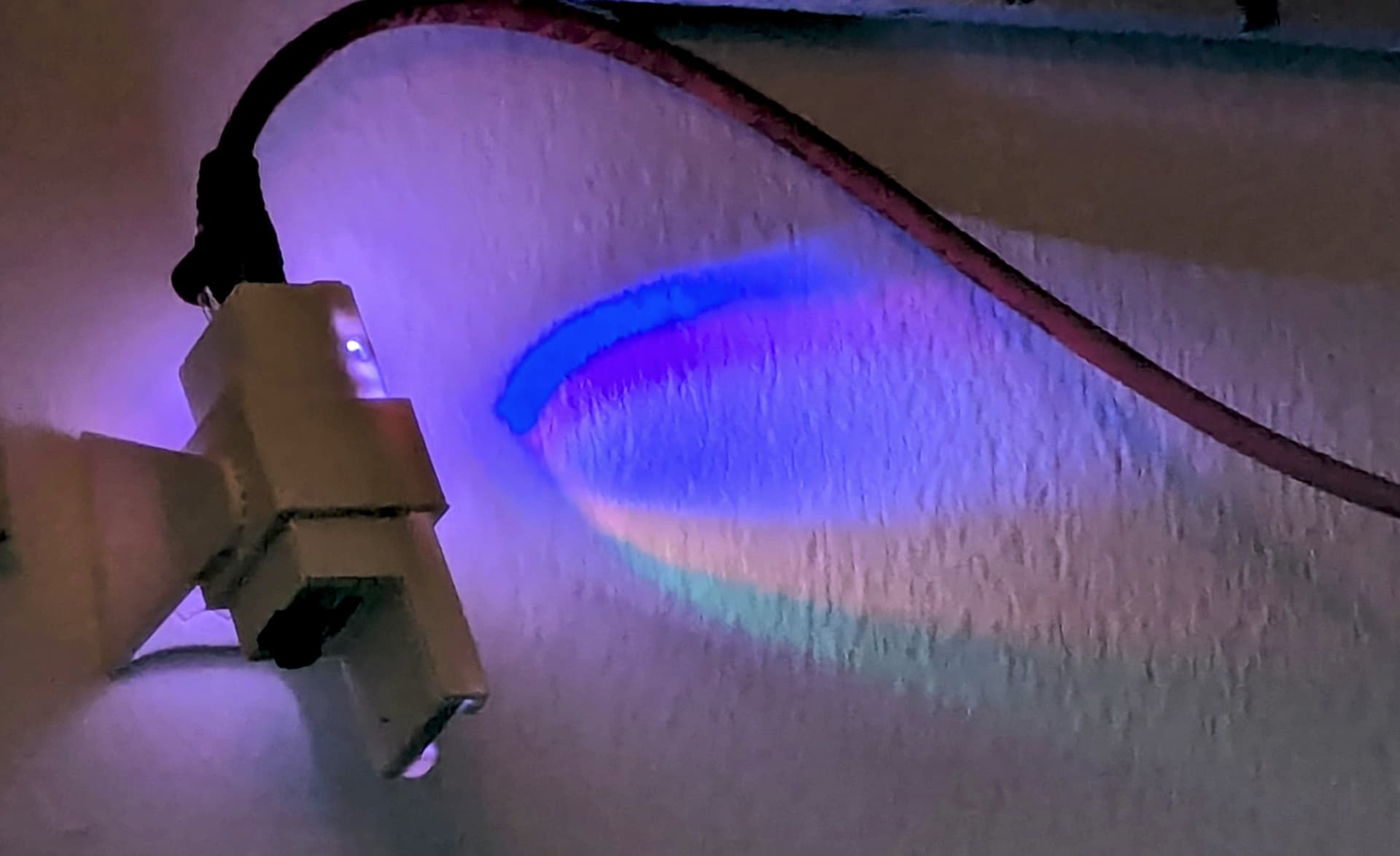
A few folks seem to have got this Waveshare ESP32-S3-Eth (no affiliation) working in HA, myself included. I have 3 of them, with the PoE Hat. No camera, very reliable vs Wifi.
There’s a few yaml’s around (here, here and here) to get folks started.
This post is about a case for the wee beastie, without camera. I found one on Thingiverse for the non-PoE Hat version (which I stupidly only discovered after I had 4 test cases printed).
So I am here to appeal for help, to make minor adjustments to the stl files, so it fits the board with the PoE Hat mounted.
So there’s a few issues at play here:
-
First off, referencing the original case stl, is that the 3D Printer folks came back and said one dimension would leave the case too thin at the Ethernet end. I don’t really see that TBH, but thought I would post it anyway, if other changes are being made.
-
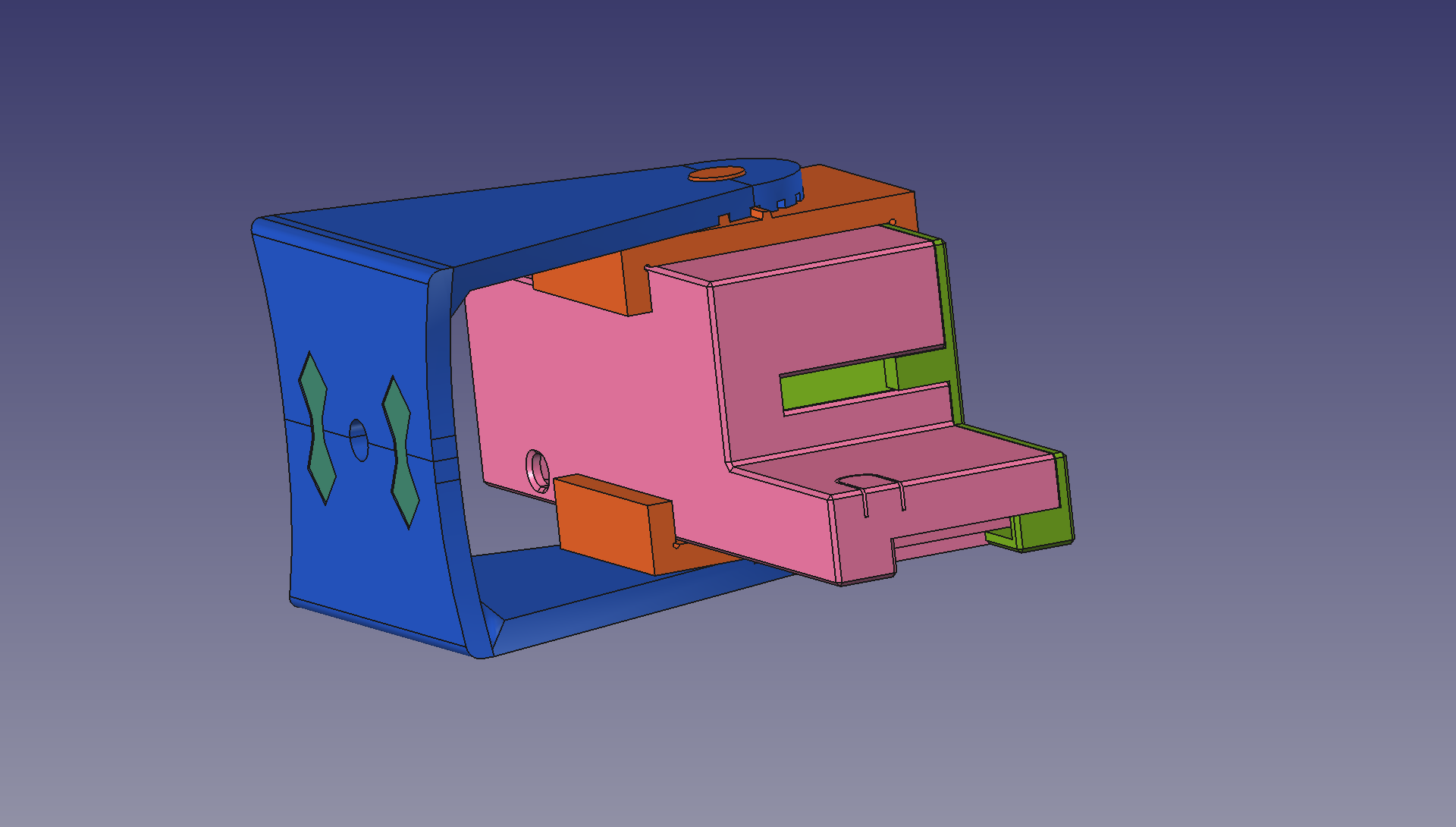
The second issue is (also referencing the original case stl) is that I found that when I put the ESP32-S3-Eth board into the case and put the lid on, there was a slight gap at one corner, at the Antenna-hole end. Referring to the picture below, this is because the square downstand “pin” is slightly too long, by about 0.3mm (say 0.4mm), causing the lid to sit slightly proud of the case, only at that corner. SEE HOWEVER POINT 4 AS THE PIN ULTIMATELY NEEDS TO BE INCREASED, NOT SHORTENED (DUE TO CASE HEIGHT INCREASE)!
-
The third issue is the case is about 0.7mm (say 0.5mm) too long for the board, meaning the board slips back and forth a bit too much. I am pretty sure that if 0.5mm was taken off the length (taken out from a location just inside the end wall of the antenna hole end), the board would still slip nicely into the case, there is still enough play. If the CASE is shortened by 0.5mm, the LID also needs to be shortened by 0.5mm, inside the pin line; so 0.5mm chopped out of the mid-point of the lid is fine.
-
The fourth and definitely the biggest issue is the addition of the PoE Hat. While the PCB board is flush with the top of the case (so still too high for the lid which has a lip) the SMD components cause the case height to be a total of 2.5mm short.
The case needs to be increased in height by about 2.5mm but should just be increased following the profile of the last 1mm at the top, not scaled up from the overall dimension. I briefly tried PrusaSlicer, (for all these changes) but the absolute or percentage increase using this software scales ALL dimensions, which means other parts of the case will go out of whack (too thick, too thin etc.).


If the case is increased by 2.5mm the lid downstand ALSO needs to be increased by 2.5mm less the 0.4mm, so the downstand in point 2 should be increased by 2.1mm.
So I guess I am appealing, somewhat unabashedly in the hope this will help others too, for someone who knows these things inside out and can do it in a 100th of the time it would take me to learn yet another bit of software (for a one-off job), to help make the changes to the original stl files. Hopefully you can see I have tried at least a bit. Thank you :-).

The STL files can be accessed using the Thngiverse link above (although at one stage an online program advised they be repaired/fixed, for what I am not sure).