I just did a write up on another thread for these hall effect sensors… or similar ones anyway… and I have already spent waaaay too much time on this today so I am going to shamelessly quote myself:
Been alive for at least 6hrs so far and still at 100%, most of that was without magnet present but it is now functioning as my water meter sensor with a ~66% magnet present duty cycle, so will be a good test, if I remember I will update at some stage on the battery situation.
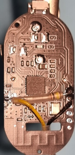
I purchased 2 different door/window sensors cause I read this thread first and people were having issues modding them… so I mapped out the other one, though it has been successfully modded above, I can see a neater way of doing it:
P1 is the wire attachment point, one is grounded, the other is mapped above.
both the external points and the hall effect sensor are connected to the same pin of the controller, so this is unfortunately not the second opening sensor being reported for this device (I was unable to find it at all, which I think has been mentioned above… it may just be a ghost… or lazy implementation)
The P1 part of the board (mapped above) is also unpopulated on my one.
Unlike my other door sensor, this one doesn’t have a stupid drain when open as its connected directly to the pin, but this also means that you need a pull up or down resistor instead of using existing.
I would suggest anyone looking to mod this one do the following (after you have confirmed that it is the same board by beeping it out):
Attach wire for external sensor to P1, this is in a good place to feed out the hole in the back panel, is easy to solder and will be stronger.
Bridge R10 (solder bridge or cut off resistor wire… or a 0ohm resistor if you are feeling fancy)
Bridge Q1 between the R10 input and D7 output (careful not to bridge to VCC)
Put a big resistor (1M would be my pick, but I haven’t tested this) in the R4 spot or in Q1 (between R10 and VCC)
If you are half decent at soldering, you could use the resistor leg to bridge the Q1 pins by adding a sharp fold the right length, then put the other side to VCC
I am going to use this one as is, so please try at your own risk, trust but verify, if in doubt beep it out… other generic or humorous caveats…
I have various needs for switched battery-powered Zigbee sensors: tilt switches, float sensors, etc. Converting reed switch door sensors is almost trivial but they’re getting hard to find. Most of the door sensors I see proclaim “Now updated with Hall Effect sensors!”
The mods of these units shown by others above achieve the aim of conversion but I get nervous with soldering onto SMD pads, as they can be very fragile. I tried a couple of conversions but wasn’t happy with them. Messy soldering and delicate connections, as expected.
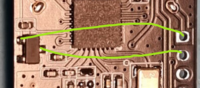
Then I got a batch of sensors with PCBs that seem a little bit more conducive to conversion. On these boards the Hall Effect sensor is at the mid-lower left. But there are five holes for header pins on the right. I wondered if they might connect to the Hall Effect sensor pins and save me soldering onto the pads. Sure enough, VCC and GND were on pins 1 and 2 and connected directly. So the only pad I needed to solder onto was the data pad. It needed a 100K resistor and a switch lead.
To give myself the best chance of a good pad connection I flattened the lead of the resistor and bent it around the PCB so it held flat against the data pad. I put heatshrink tubing around the lead to prevent shorts across the board.
Then it was a simple matter of soldering the resistor to pin 1, a lead to pin 2 and another lead to the data pin. I slid it alongside the resistor inside the heatshrink. Once it was all in place I cut off the end of the resistor lead that wrapped around the PCB.
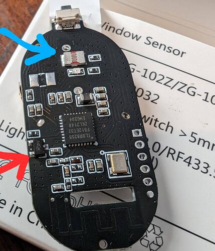
I got this batch of door sensors from Ali Express, where you can never quite tell what you’re getting until they arrive. The boxes say “Model: ZG-102ZL/ZG-102Z” and the PCB is labeled “ZG-102Z”, if that helps.
The board you have looks to be almost identical to mine, with the addition of what appears to be a Light Dependent Resistor. At a guess, you have the ZG-102ZL, with the ‘L’ indicating the add-on LDR.
I’d remove just the Hall Effect sensor (red arrow) and leave the LDR (blue arrow) in place. Only remove the LDR if the switch won’t work after modding. Also, confirm the continuity between the pads and pins before proceeding, just to be sure.