ABS enclosure with 4 x AA battery compartment (UK) Anyone?

Hi all

Mrs BB LOVES her garden lights but HATES cables and power supplies.

HA She likes as she can control her beloved lights from her phone

SO… I have ordered the bits to prototype up the circuit illustrated:

Amazingly, No one seems to sell an ABS enclosure with a 4 X AA battery compartment anymore ?
I can find 9V PP3 compartment cases 2 a penny - but not a single one with a built in compartment for 4 x AA / C / D cells

I know they existed around 2004-2006 but now I cant find a single one after extensive google / amazon / ebay trawling. Obviously the bigger the batteries the longer it will run between changes but Mrs BB wont adopt a solution that you need to take a screwdriver to. It needs a snap on / off lid , pull out the flat , push in the charged and away we go again.

There are battery boxes galore too. but they dont have space for the ZigBee relay.

Anyone out there know of a case that fits the bill please ?

Many thanks in advance

Regards

BB

How long do you expect 4-AA batteries to run an esp, wifi or bluetooth, 2 relays, and a string of lights?

My estimate you will be replacing the batteries once a day. Maybe twice if you actually use the lights.

2 Likes

I dont know - and hence the use of the word “prototype” and the possibility of using C or D cells :wink:

The AA batteries I plan to test are rated 3200mAH and seem in spec from tests.

The Leds run for a month or more on 2 x AA batteries until the light sensor in their original box died

I could replace the AA’s, for example, with a 5V 22AH USB powerbank which would work for my good lady but but the hardware side becomes “too much fuss” if she cannot simply swap the batteries in a box and my chances of finding an ABS box that has a toolless removable battery compartment lid to take a high capacity USB powerbank without resorting to screwdrivers for access is about as much chance as finding Lord Lucan delivering for Just Eat whilst riding Shergar!

But if you know of:

  • A COTS battery box
  • With built in USB charging and reasonably high current lithium cell
  • And enough space inside after all that to take a ZigBee relay and voltage divider

Then I am open to suggestions ?

Regards

BB

You are sure this is better than burying a low voltage landscape wire out to the garden. You don’t have to use the low voltage lights, just use the power source.

You said you are in zigbee range, so it can’t be very far away.

Sadly the answer is an unquestionable YES ! it is better

the garden is about 100 ft long but downhill on a 1 in 2.5 slope. Its all terraced . 1 coordinator and 2 ZigBee repeaters serve the area very effectively . we have no additional capacity for Wi-Fi due to the sheer number of access points visible from this hilltop (between 35 and 72 dependent upon the weather)

Also as I am heavily involved in radio communication (both Amateur and Professional) spectrally dirty cheap power supplies are a no-no. I have had to plant my most susceptible antennas at the foot of the garden to get away from electrical noise generated by my neighbours, council funded Solar installs with dubious quality inverters and leakage from Virgin Medias cable system that runs in the street at the top of the hill.

So ZigBee and a high capacity battery are the only feasible option

Regards

BB

1 Like

So… I agree. Don’t expect long lasting batteries.

There is a few things you could consider.
Can the lights take 3 volts instead? (two AA batteries).
That would mean less consumption by the voltage divider.

If it does not work with 3 volts, then I suggest you move the voltage divider to after the relay since then at least it will only consume when the lights are on.
But then again, that consumption is probably negligible compared to the relay.

Are you looking for something like this? https://www.aliexpress.com/item/1005002253219208.html

@Hellis81

Absolutely ! I realised that the divider needed to be on the output of the relay about 3 hours after I had posted :slight_smile: - but many thanks for pointing it out ! If I can still edit the diagram in the first post I will update it for anyone following my approach, or post a final circuit as an epilogue.

@Shadowfist

Thanks for the link . Dedicated battery boxes are readily available far and wide, but have no room for additional circuitry.

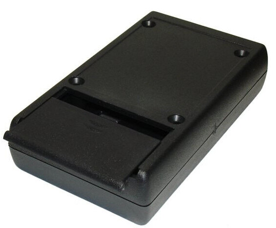
From a cosmetic point of view, what I am looking for is something like this:

image

But in this image, the battery compartment only holds a PP3 (9V square battery)

I am seeking a box (or indeed a range of boxes) with a battery compartment that can hold either 4 x AA , 4 x C or 4 x D cells and still have room for the ZigBee relay and additional circuitry.

Even if I end up buying 3 boxes its not a problem as there are numerous other “projects” that they can be deployed into.

Regards

BB

Just get a battery holder, and one of these:

image

No tools, very cheap, large variety of sizes

1 Like

Yes I have done that before (e.g. a “Sun Simulator” for charging my Motorhome leisure batteries at night / in winter using the MPPT solar controller instead of installing a 240V socket on our driveway)

But:

  • I dont think it would obtain the much coveted “Certificate of Spouse Compliance

  • With the changes in outdoor temperature the lids are, in my own experience, forever popping off (even the latched ones) resulting in excessive water ingress even though there are case holes to stop air pressure build up.

Therefore I am seeking a project box (as its spouse acceptable) with a battery compartment so that there is no need for tools to change the batteries

Regards

BB

Seems to me like a perfect excuse/reason to get a 3d printer and design and print a box that fits your needs exactly ?

ooh! I wish . Maybe in a few years once the backlog of projects is a little smaller

Or design what you want and get it printed online

Yah same idea here. Have you considered just printing it? You can just download a battery box.

Just get a IP65 junction box on Amazon.uk there are plenty available, something like this
Amazon.co.uk

You can also buy a filtered power supply for low voltage (12v and 24v), will probably be better for long term.

He’s right, you can’t mix ham radio and long lead power wires, DC or not…

The power lead will pick up the RF and the noise will be picked up by the antenna…

I think the HF noise from the LEDs will cause problems as well, but if free floating not gnd referenced, maybe…

Veering off my own topic a bit - as it may be of interest to those following the thread…

I built the Version 2 prototype with 4 x NiMH D cells that I already had (10AH cells)

I dispensed with the voltage divider , and as a quick and dirty and took a second feed off the battery pack:

remember guys this a quick and dirty prototype not final production build !!

Paired the ZigBee relay (it retains its settings after power down - awesome! )
Set the relay action to latching (press the top button this setting is also retained at power down)

And I flicked the switch in HA …

Every other LED lit up !

On closer inspection the LED string is wired (where V or ^ indicates LED current flow)

--------------------------------------------------+ 2.5V
V ^ V ^ V ^ V ^ V ^ V ^
--------------------------------------------------Gnd

the original controller unit (defunct and sealed with potting compond) switched the DC polarity At 3 speeds:

  1. Slow flash
  2. fast flash
  3. Always on

But that “always on” state was faked by fast switching the polarity - amazed that it didn’t produce radio interference but verified that with a spectrum analyser some years ago when it was new.

So to make my prototype work as planned (So I can assess potential interference and current consumption) I have 2 options:

Option1) rewire the LED string to make all the diodes flow V V V V (Mrs BB doesnt like them flashing anyway)

Option 2) insert a small H bridge circuit (#) (4 x FETs and a few discretes) in between the relay and the LEDs to invert the DC polarity fast enough to make it look as if they are steady on.

Option 1) is guaranteed to upset missus BB! It would be better to make a new string up and simply swap them out

Option 2) draws more battery power to drive the H Bridge but , potentially (if I get the switching frequency right) is only drawing full LED power for 50 % of the cycle and we dont need the LEDs to be any brighter than they were. However I would in all probability need a mix 43 ferrite bead on the H bridge output to stop spurious emissions out into the radio spectrum.

Currently looking at a few low cost COTS H bridge boards from China . Will post again with details as to how it works out and how long the LEDs last on a charge

regards

BB

(#) thanks to “Bernie” for the Tip! - I figured it must exist but didn’t know what the circuit was called

1 Like

after some coffee break research I have decided to try these H Bridge devices from Fleabay:

image

its not a big string of LEDs and 2 of these devices came in at under a fiver. they will run from 2.5v
as well and I can potentially use them to drive 2 short LED strings (which may yet prove good enough)

And if it doesnt work , well, its still less than the cost of a pint in most UK cities these days and I would drink that , then flush it down the loo !

Regards

BB