Hello All,
I have been battling with this for a few weeks, and I was just wondering if someone might be able to provide a bit of assistance and advice. I am trying to get a ESP32 and ESPhome going to allow control of my Actron Air conditioner with a AM7 wall controller via home assistant.
I am basing my Esphome code and wiring off this similar project using a esp32 and Arduino code https://github.com/kursancew/actron-air-wifi
However I am having issues getting this working with Esphome and home assistant, I am a bit of an electronics newbie so not sure if I am doing something wrong, or missing something obvious.
Quick sketch of my current wiring for my setup below. which is very similar to the GitHub wiring diagram.

I am using the following parts based of the initial GitHub project as well.
1 x ESP-WROOM-32
1 x GP8403 DAC
1 x BC548 NPN Transistor
1 x 20k Ohm Reistor
1 x Arduino Voltage Sensor similar to this.
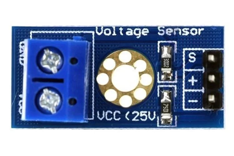
I have the esp32 hooked up to a gp8403 to be used as the DAC and then have output 0 from the DAC connected a 20k ohm 0.5 watt resistor connecting it to the base pin on the BC548 NPN transistor. I have the key wire from the wall panel connected to the collector on the 548 transistor and the emitter connected up to the VCC input on a 0-25V DC Arduino Voltage Sensor which is just a voltage divider.
However this doesn’t appear to be working as I would suspect. I have created a bunch of switches in Esphome that set the DAC output to restrict the voltage flowing via the 548 transistor to match the corresponding voltage that a keypress on the wall control panel does and and I can see the voltage drop on the voltage sensor matching what a keypress would when enabling these switches in home assistant. But the physical wall panel controls never updates to reflect any of the changes that I initiate via home assistant.
If I press the keypad buttons on the physical wall panel, I can see the voltage drops on the voltage sensor and the wall panel updates correctly to reflect these changes which has me a bit confused why the controls via the Esphome and 548 transistor don’t work as I see close to the the same voltage drops when using the ESPhome switches via home assistant in the ESPhome logs for the voltage sensor.
My ESPHome code is below
esphome:
  name: aircon
  friendly_name: Aircon
  on_boot:
      then:
        - switch.turn_on: constant_output_5v


esp32:
  board: esp32dev
  framework:
    type: arduino

# Enable logging
logger:
 level: DEBUG

# Enable Home Assistant API
api:
  encryption:
    key:

ota:
  password:

wifi:
  ssid: !secret wifi_ssid
  password: !secret wifi_password

# Enable fallback hotspot (captive portal) in case wifi connection fails
  ap:
    ssid: "Aircon-Test Fallback Hotspot"
    password: ""

captive_portal:

#Number Component
number:
  - platform: template
    name: "Aircon Temp"
    id: aircon_numb_temp
    optimistic: true
    min_value: 17
    max_value: 30
    step: 0.5
    unit_of_measurement: “°C”


#Enable sensor to read external button Voltages
#https://esphome.io/components/sensor/adc.html?highlight=gpio+sensor
sensor:
  - platform: adc
    pin: GPIO32
    name: "Aircon Wall Panel - Key Press"
    update_interval: 50ms
    accuracy_decimals: 3
    filters:
    - multiply: 5.0
  - platform: homeassistant
    id: current_temperature_downstairs
    entity_id: sensor.lumi_lumi_sensor_ht_temperature


#Setup i2c bus to controll gp8403
#https://esphome.io/components/i2c#i2c
i2c:
  sda: 21
  scl: 22
  scan: true
  id: bus_a

#GP8403 output to Send Voltages for key presses
#https://esphome.io/components/output/gp8403
gp8403:
  id: my_gp8403
  voltage: 5V
  address: 0x5F

output:
  - platform: gp8403
    id: my_gp8403_output_1
    gp8403_id: my_gp8403
    channel: 0
  - platform: gp8403
    id: my_gp8403_output_2
    gp8403_id: my_gp8403
    channel: 1

switch:
#Contant 5v Output Switch
  - platform: output
    output: my_gp8403_output_2
    name:  Constant 5v Output Switch
    id: constant_output_5v
    on_turn_on:
        - output.set_level:
            id: my_gp8403_output_2
            level: 100%
    on_turn_off:
         - output.set_level:
            id: my_gp8403_output_2
            level: 0%


# Temp Up Switch
# Output Voltage 1.509 V
  - platform: output
    output: my_gp8403_output_1
    name:  Switch Temp Up
    id: switch_temp_up
    icon: "mdi:thermometer-chevron-up"
    on_turn_on:
        - number.increment:
            id: aircon_numb_temp
            cycle: false
        - output.set_level:
            id: my_gp8403_output_1
            level: 42.2%
        - delay: 800ms
        - switch.turn_off: switch_temp_up
    on_turn_off:
         - output.set_level:
            id: my_gp8403_output_1
            level: 100%

# Temp Down Switch
# Output Voltage 2.872 V
  - platform: output
    output: my_gp8403_output_1
    name:  Switch Temp Down
    id: switch_temp_down
    icon: "mdi:thermometer-chevron-down"
    on_turn_on:
        - number.decrement:
            id: aircon_numb_temp
            cycle: false
        - output.set_level:
            id: my_gp8403_output_1
            level: 68.7%
        - delay: 800ms
        - switch.turn_off: switch_temp_down
    on_turn_off:
        - output.set_level:
            id: my_gp8403_output_1
            level: 100%

# Aircon Mode Switch
# Output Voltage  0.452 V
  - platform: output
    output: my_gp8403_output_1
    name:  Switch AC Mode
    id: switch_mode
    icon: "mdi:home-thermometer-outline"
    on_turn_on:
        - output.set_level:
            id: my_gp8403_output_1
            level: 19.4%
        - delay: 800ms
        - switch.turn_off: switch_mode
    #on_turn_off:
        - output.set_level:
            id: my_gp8403_output_1
            level: 100%

# Fan Mode Switch
# Output Voltage 3.220 V
  - platform: output
    output: my_gp8403_output_1
    name:  Switch Fan Mode
    id: switch_fan_mode
    icon: "mdi:fan"
    on_turn_on:
        - output.set_level:
            id: my_gp8403_output_1
            level: 73.9%
        - delay: 800ms
        - switch.turn_off: switch_fan_mode
    #on_turn_off:
        - output.set_level:
            id: my_gp8403_output_1
            level: 100%

# Zone Down Staris Switch
# Output Voltage 3.650 V
  - platform: output
    output: my_gp8403_output_1
    name:  Switch Down Stairs
    id: switch_down_staris
    icon: "mdi:stairs-down"
    on_turn_on:
        - output.set_level:
            id: my_gp8403_output_1
            level: 84.5%
        - delay: 800ms
        - switch.turn_off: switch_down_staris
    on_turn_off:
        - output.set_level:
            id: my_gp8403_output_1
            level: 100%

# Output Voltage 3.875 V
# Zone Up Staris Switch
  - platform: output
    output: my_gp8403_output_1
    name:  Switch Up Stairs
    id: switch_up_staris
    icon: "mdi:stairs-up"
    on_turn_on:
        - output.set_level:
            id: my_gp8403_output_1
            level: 88.9%
        - delay: 800ms
        - switch.turn_off: switch_up_staris
    on_turn_off:
        - output.set_level:
            id: my_gp8403_output_1
            level: 100%

#Aircon On/Off Switch
# Output Voltage 0.000 V
  - platform: output
    output: my_gp8403_output_1
    name:  Switch On/Off
    id: switch_ac_on_off
    icon: "mdi:power"
    on_turn_on:
        - output.set_level:
            id: my_gp8403_output_1
            level: 0%
        - delay: 800ms
        - switch.turn_off: switch_ac_on_off
    on_turn_off:
        - output.set_level:
            id: my_gp8403_output_1
            level: 100%
Here is an example of the logs from ESPhome with me using one of the homeassitant switches as well as pressing the physical buttons on the control panel.
[19:05:42][D][switch:012]: 'Switch Temp Down' Turning ON.
[19:05:42][D][switch:055]: 'Switch Temp Down': Sending state ON
[19:05:42][D][number:088]: 'Aircon Temp' - Decrement number, without cycling
[19:05:42][D][number:113]:   New number value: 17.000000
[19:05:42][D][number:012]: 'Aircon Temp': Sending state 17.000000
[19:05:42][D][sensor:094]: 'Aircon Wall Panel - Key Press': Sending state 2.87000 V with 3 decimals of accuracy
[19:05:42][D][sensor:094]: 'Aircon Wall Panel - Key Press': Sending state 2.87500 V with 3 decimals of accuracy
[19:05:42][D][sensor:094]: 'Aircon Wall Panel - Key Press': Sending state 2.89000 V with 3 decimals of accuracy
[19:05:42][D][sensor:094]: 'Aircon Wall Panel - Key Press': Sending state 2.88000 V with 3 decimals of accuracy
[19:05:42][D][sensor:094]: 'Aircon Wall Panel - Key Press': Sending state 2.87000 V with 3 decimals of accuracy
[19:05:42][D][sensor:094]: 'Aircon Wall Panel - Key Press': Sending state 2.86000 V with 3 decimals of accuracy
[19:05:42][D][sensor:094]: 'Aircon Wall Panel - Key Press': Sending state 2.88500 V with 3 decimals of accuracy
[19:05:42][D][sensor:094]: 'Aircon Wall Panel - Key Press': Sending state 2.87500 V with 3 decimals of accuracy
[19:05:42][D][sensor:094]: 'Aircon Wall Panel - Key Press': Sending state 2.86000 V with 3 decimals of accuracy
[19:05:42][D][sensor:094]: 'Aircon Wall Panel - Key Press': Sending state 2.87500 V with 3 decimals of accuracy
[19:05:42][D][sensor:094]: 'Aircon Wall Panel - Key Press': Sending state 2.85000 V with 3 decimals of accuracy
[19:05:43][D][sensor:094]: 'Aircon Wall Panel - Key Press': Sending state 2.86000 V with 3 decimals of accuracy
[19:05:43][D][sensor:094]: 'Aircon Wall Panel - Key Press': Sending state 2.87000 V with 3 decimals of accuracy
[19:05:43][D][sensor:094]: 'Aircon Wall Panel - Key Press': Sending state 2.87500 V with 3 decimals of accuracy
[19:05:43][D][sensor:094]: 'Aircon Wall Panel - Key Press': Sending state 2.87500 V with 3 decimals of accuracy
[19:05:43][D][sensor:094]: 'Aircon Wall Panel - Key Press': Sending state 2.86500 V with 3 decimals of accuracy
[19:05:43][D][sensor:094]: 'Aircon Wall Panel - Key Press': Sending state 2.88500 V with 3 decimals of accuracy
[19:05:43][D][switch:016]: 'Switch Temp Down' Turning OFF.
[19:05:43][D][switch:055]: 'Switch Temp Down': Sending state OFF

Output from a Physical button press on the wall panel below.


[19:05:51][D][sensor:094]: 'Aircon Wall Panel - Key Press': Sending state 2.90000 V with 3 decimals of accuracy
[19:05:51][D][sensor:094]: 'Aircon Wall Panel - Key Press': Sending state 2.88500 V with 3 decimals of accuracy
[19:05:51][D][sensor:094]: 'Aircon Wall Panel - Key Press': Sending state 2.87500 V with 3 decimals of accuracy
[19:05:51][D][sensor:094]: 'Aircon Wall Panel - Key Press': Sending state 2.88000 V with 3 decimals of accuracy
[19:05:51][D][sensor:094]: 'Aircon Wall Panel - Key Press': Sending state 2.90500 V with 3 decimals of accuracy
[19:05:51][D][sensor:094]: 'Aircon Wall Panel - Key Press': Sending state 2.87500 V with 3 decimals of accuracy
[19:05:51][D][sensor:094]: 'Aircon Wall Panel - Key Press': Sending state 4.41000 V with 3 decimals of accuracy
I am not sure what I am doing wrong here as it appears that this should all work but I must be missing something obvious.
For testing and just to make sure everything should work as intended I have created some other Esphome code below removing the BC548 NPN Transistor and, 20k Ohm Resistor and Arduino Voltage Sensor and have the output of the DAC directly connected to the key wire on the wall panel. And this appears to work fine I can send the corresponding voltage for each keypress that I am interested in and the wall panel correctly updates to reflect these changes. However the physical key panel buttons no longer works with this setup. I assume this might be due to me sending a constant 4.9-5v from the ESP32 on boot and the keypress not being able to reduce the resistance/voltage when I press the physical keys.
Example of the somewhat working ESPhome code below.
esphome:
  name: aircon
  friendly_name: Aircon
  on_boot:
      then:
        - output.set_level:
           id: my_gp8403_output_1
           level: 98%

esp32:
  board: esp32dev
  framework:
    type: arduino

# Enable logging
logger:
 level: DEBUG

# Enable Home Assistant API
api:
  encryption:
    key:

ota:
  password:

wifi:
  ssid: !secret wifi_ssid
  password: !secret wifi_password

  # Enable fallback hotspot (captive portal) in case wifi connection fails
  ap:
    ssid: "Aircon-Test Fallback Hotspot"
    password: "bxbGyGC7zQA2"

captive_portal:

#Number Component
number:
  - platform: template
    name: "Aircon Temp"
    id: aircon_numb_temp
    optimistic: true
    min_value: 17
    max_value: 30
    step: 0.5
    unit_of_measurement: “°C”

#Enable sensor to read external button Voltages
#https://esphome.io/components/sensor/adc.html?highlight=gpio+sensor
sensor:
  - platform: adc
    pin: GPIO32
    name: "Aircon Wall Panel - Key Press"
    update_interval: 10ms
    accuracy_decimals: 3
    filters:
    - multiply: 5.0
    #- offset: -0.375
    on_value_range:
      - below: 5.00
        above: 3.80
        then:
          - logger.log: "Zone Up Stairs Test Button Press"
          #- button.press: aircon_zone1_button
  - platform: homeassistant
    id: current_temperature_downstairs
    entity_id: sensor.lumi_lumi_sensor_ht_temperature


#Setup i2c bus to controll gp8403
#https://esphome.io/components/i2c#i2c
i2c:
  sda: 21
  scl: 22
  scan: true
  id: bus_a

#GP8403 output to Send Voltages for key presses
#https://esphome.io/components/output/gp8403
gp8403:
  id: my_gp8403
  voltage: 5V
  address: 0x5F

output:
  - platform: gp8403
    id: my_gp8403_output_1
    gp8403_id: my_gp8403
    channel: 0
    min_power: 0.01
  - platform: gp8403
    id: my_gp8403_output_2
    gp8403_id: my_gp8403
    channel: 1


# Button Configuration
button:
#Temp Up Button
  - platform: output
    name: Aircon Temp Up
    id: aircon_temp_up_button
    duration: 10ms
    output: my_gp8403_output_1
    # Optional variables:
    icon: "mdi:thermometer-chevron-up"
    on_press:
     then:
      - switch.turn_on: switch_temp_up

#Temp Down Button
  - platform: output
    name: Aircon Temp Down
    id: aircon_temp_down_button
    duration: 10ms
    output: my_gp8403_output_1
    # Optional variables:
    icon: "mdi:thermometer-chevron-down"
    on_press:
     then:
      - switch.turn_off: switch_temp_down

#Fan Button Modes
  - platform: output
    name: Aircon Fan
    id: aircon_fan_button
    duration: 10ms
    output: my_gp8403_output_1
    # Optional variables:
    icon: "mdi:fan"
    on_press:
     then:
      - switch.turn_on: switch_fan_mode


#Zone Down Staris Mode
  - platform: output
    name: Aircon Zone Down Staris
    id: aircon_zone1_button
    duration: 10ms
    output: my_gp8403_output_1
    # Optional variables:
    icon: "mdi:stairs-down"
    on_press:
     then:
      - switch.turn_on: switch_down_staris


#Zone Up Staris Mode
  - platform: output
    name: Aircon Zone Up Staris
    id: aircon_zone2_button
    duration: 300ms
    output: my_gp8403_output_1
    # Optional variables:
    icon: "mdi:stairs-up"
    on_press:
     then:
      - switch.turn_on: switch_up_staris


#Aircon Mode
  - platform: output
    name: Aircon Mode
    id: aircon_mode_button
    duration: 300ms
    output: my_gp8403_output_1
    # Optional variables:
    icon: "mdi:home-thermometer-outline"
    on_press:
     then:
      - switch.turn_on: switch_mode


#Aircon On/Off
  - platform: output
    name: Aircon On/Off
    id: aircon_on_off
    duration: 300ms
    output: my_gp8403_output_1
    # Optional variables:
    icon: "mdi:power"
    on_press:
     then:
       - switch.turn_off: switch_ac_on_off


switch:
#Temp Up Switch
  - platform: output
    output: my_gp8403_output_1
    name:  Switch Temp Up
    id: switch_temp_up
    icon: "mdi:thermometer-chevron-up"
    on_turn_on:
        - number.increment: aircon_numb_temp
        - output.set_level:
            id: my_gp8403_output_1
            level: 30%
        - delay: 300ms
        - switch.turn_off: switch_temp_up
    on_turn_off:
         - output.set_level:
            id: my_gp8403_output_1
            level: 98%

#Temp Down Switch
  - platform: output
    output: my_gp8403_output_1
    name:  Switch Temp Down
    id: switch_temp_down
    icon: "mdi:thermometer-chevron-down"
    on_turn_on:
        - number.decrement: aircon_numb_temp
        - output.set_level:
            id: my_gp8403_output_1
            level: 56%
        - delay: 300ms
        - switch.turn_off: switch_temp_down
    on_turn_off:
        - output.set_level:
            id: my_gp8403_output_1
            level: 98%
#Aircon Mode Switch
  - platform: output
    output: my_gp8403_output_1
    name:  Switch AC Mode
    id: switch_mode
    icon: "mdi:home-thermometer-outline"
    on_turn_on:
        - output.set_level:
            id: my_gp8403_output_1
            level: 8%
        - delay: 300ms
        - switch.turn_off: switch_mode
    #on_turn_off:
        - output.set_level:
            id: my_gp8403_output_1
            level: 98%
#Fan Mode Switch
  - platform: output
    output: my_gp8403_output_1
    name:  Switch Fan Mode
    id: switch_fan_mode
    icon: "mdi:fan"
    on_turn_on:
        - output.set_level:
            id: my_gp8403_output_1
            level: 65.5%
        - delay: 350ms
        - switch.turn_off: switch_fan_mode
    #on_turn_off:
        - output.set_level:
            id: my_gp8403_output_1
            level: 98%
#Zone Down Staris Switch
  - platform: output
    output: my_gp8403_output_1
    name:  Switch Down Stairs
    id: switch_down_staris
    icon: "mdi:stairs-down"
    on_turn_on:
        - output.set_level:
            id: my_gp8403_output_1
            level: 72%
        - delay: 300ms
        - switch.turn_off: switch_down_staris
    on_turn_off:
        - output.set_level:
            id: my_gp8403_output_1
            level: 98%
#Zone Up Staris Switch
  - platform: output
    output: my_gp8403_output_1
    name:  Switch Up Stairs
    id: switch_up_staris
    icon: "mdi:stairs-up"
    on_turn_on:
        - output.set_level:
            id: my_gp8403_output_1
            level: 76%
        - delay: 300ms
        - switch.turn_off: switch_up_staris
    on_turn_off:
        - output.set_level:
            id: my_gp8403_output_1
            level: 98%
#Aircon On/Off Switch
  - platform: output
    output: my_gp8403_output_1
    name:  Switch On/Off
    id: switch_ac_on_off
    icon: "mdi:power"
    on_turn_on:
        - output.set_level:
            id: my_gp8403_output_1
            level: 0%
        - delay: 300ms
        - switch.turn_off: switch_ac_on_off
    on_turn_off:
        - output.set_level:
            id: my_gp8403_output_1
            level: 98%
My ideal setup would allow me to still use the physical wall control panel for easy of use of my wife and kids. However I would also like to be send controls via home assistant and the Esphome which is what I was hoping I would be able to achieve with the schematics based on the Github project but I just can’t seem to get that to work as I was hoping it would.
Any advice or assistant would be greatly appreciated!


