Add Smart Control to Your Awning with an ESP8266 and Home Assistant

By integrating an ESP8266 into our Becker Centronic awning remote, we have successfully automated our awning and enabled control within Home Assistant.

To automate the awning, we installed a USB-powered ESP8266 into the existing awning remote. This allows the remote to be triggered by the ESP8266, which adjusts the awning’s position. The microcontroller also powers the remote, eliminating the need for batteries and ensuring the system runs reliably and consistently. This not only saves you the hassle of constantly changing batteries, but it also reduces waste and helps to make your home more eco-friendly.

smart_awning

More details, Arduino code, and bill of materials can be found in our blog How to Add Smart Control to Your Awning with an ESP8266 and Home Assistant

2 Likes

Can I see how you have the other side of your ESP8266 board wired up? Planning on a similar project to control a mosquito misting system.

Thanks for sharing, im trying to control a small fan doing the same and have a few questions. I my button has one pin on either side that provides a standard 5v and pressing the button seems to drop the voltage so this is normally closed but open with the button.
Would this work as you have connected this ? If so which lead did yo solder to ? I assume it doesn’t matter so long as it’s the connectors that interrupt the 5v signal ?
Thanks

Hi milsky99,
Fans usually don’t use encrypted IR signals. It is quite unlikely that with your remote, you would turn on all fans in the neighbourhood. So, try an IR blaster (aliexpress search for Tuya wifi smart IR remote control) first. That would make things easier.
In general, as I learned with my project to replicate the smart awning project, yes, you can make the esp32 board do a voltage drop or boost. So either it can be on continuously and off for a moment when the button is pushed, and the other way around (off continuously and on for a moment when you push a button).

Hi Freddie,

really nice solution. With percentage included, perfect! Good work! :+1:
Stupid question: Is it still possible to use the physical buttons? And if so, will this be detected and the status adjusted in HomeAssistant?

Thanks a lot!
Best regards from Bavaria,
Bernd

Thanks very much @fleeman
I have read your blog more than 10 times during the time I was doing the similar thing. It is very useful.

  1. I have done it against a remote from WISTAR model RE301
  2. I have spent some time to confirm the points to solder and the voltage to control using a multimeter
  3. I am also using d1 mini, but I eventually didnt draw the power from the remote, as the remote triggered some odd led pattern when connecting the power to 3v3 pin, so, I only wire the gnd, but getting the power from usb-c
  4. I didnt program using Arduino, instead, I used esphome to setup the gpio switches on D5/6/7. But I configured based on your scripts as well, which is inverted (active low) and turned off after 500ms. Certainly, I confirm it in point 2 above.

Now, I have a smart awning. :smiley:

1 Like

Yes, you can still use the physical buttons. For now, the button presses are not registered, but this is technically possible, so we’ll might add that in a future release.

Well done! Glad we could help you on your journey!

I finally got it working too, but not quite like Freddie’s setup.

I ditched the ESP32-C6 DecKitC-1-N4 and also that Hailege optocoupler.
The miniD1 and all its brothers and sisters were causing problems on my wifi6 network so a C6 with wifi6 support was much needed.

USB-C powered, to the resistor, to the optocoupler.
Other side of the optocoupler 2 wires, one to each leg of the button.

Buttons on the remote still work.
The buck converter makes the battery redundant as it nicely converts either 5v or 3.3v coming from the ESP32-C6 to a steady 3v that is required by the remote.

But this is more like an experimental setup as many wires are needed.

Now I’ve gained a little bit more insights in volts and currents etc. I finally understand how Freddie originally made this work with only wiring one leg of each button. Keeping the current UP and at the push of the button shortly dropping DOWN the current is how you need only one wire. Still, as the current coming from the ESP32 board is 3.3v and not 3v which, on my remote, caused issues.

I used ESP-DIF to programme the ESP32-C6 and it includes a percentage open/close situation.

Thanks @fleeman for the inspiration and the many many many hours of fiddling, botching everything up and starting again :slight_smile:

Would you mind sharing your esphome code? I am trying to make my awning smart and was thinking that esphome would be easier to manage in my setup than a static arduino sketch.

Thanks a lot!

I finally mastered the one-wire setup Freddie showed at the start of this topic too (besides the 2 wire setup using optocouplers - see earlier post), albeit with a twist. I’ve spelled it out below, because the pictures of Freddie left a bit too much to the imagination if you are a complete idiot (like me) when it comes to volts and soldering and stuff. As a consequence it took me one and half year (with pauses) to complete this and not Freddie’s 1,5 hour. But I got there in the end and had some fun (and lots of frustration) along the way. Hope that someone feels inspired to get soldering and, foremost, to get yourself an ESP32 and start playing with them, they are awesome.

Here are the schematics, a final picture, the shopping list (with links to AliExpress) and the ESP-IDF code (not Arduino).

Shopping List:

  1. Seeed Studio XIAO ESP32C6 (because it is small and wifi6)
  2. 3.3-6V to 3V DC-DC Step-Down Power Supply Buck LDO Module Voltage regulator Board (because the Seeed board spits out 3.3V and the remote operates at 3.0V)
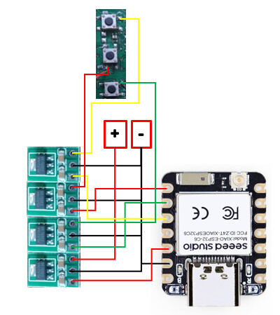
Schematics

So, the Seeed Xiao ESP32-C6 puts 3.3V as an output to the GPIO port(s) and of course to the 3.3v power output. The remote operates with 2 AAA batteries meaning 3.0V, hence the buck converters.
The first (lowest) converter provides the remote with uninterrupted 3v power. The second from the bottom feeds a continuous 3v to the + of the OPEN button and is interrupted when the button is pressed in Home Assistant. The 3rd operates the STOP button and the 4th operates the CLOSE button in a similar way. The wires are connected to the + legs (use multimeter) of each button. Middle whole of each converter and the lowest connection on the ESP32 (closest to USB-C port) are all negatives (black wires) and are all coming/soldered together to the minus of the remote. The physical buttons of the remote still work once you’ve soldered the stuff together.

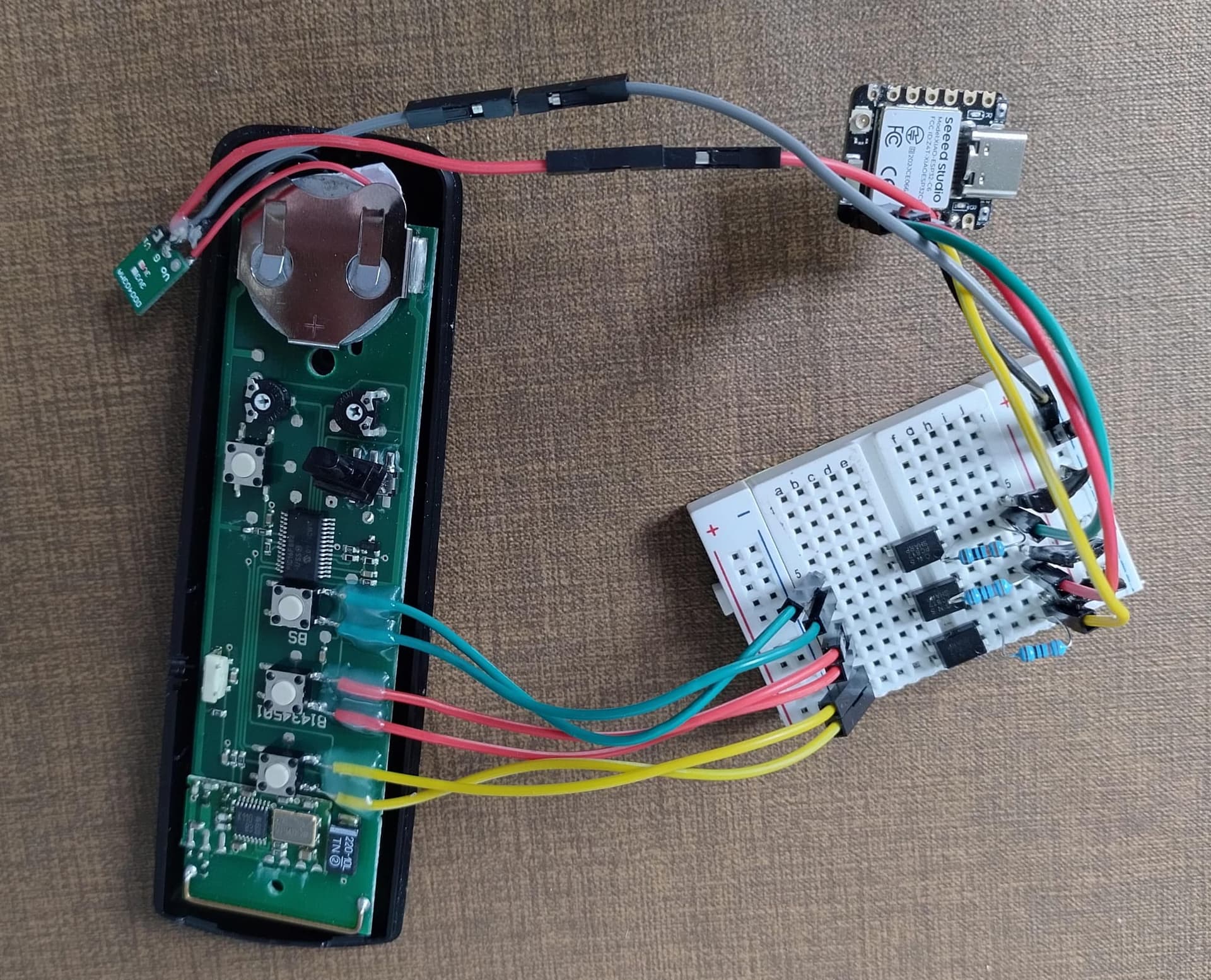
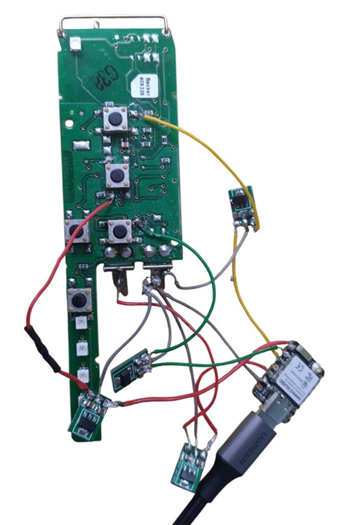
This does not look so nice as in the schematics, but with the knowledge I have now, I would first glue the buck converters to some carton or plastic, nice and tidy together, then solder the wires (for which I used wires from a CAT6 POE cable) to the converters, glue them as well, so they can’t move and then fit the whole inside the remote opening where the batteries were. Lastly then to solder the wires to the ESP32 and the buttons on the board and also place the esp32 inside the remote housing. It should nicely fit, there is enough space.

main.c code

#include <stdio.h>
#include "freertos/FreeRTOS.h"
#include "freertos/task.h"
#include "freertos/timers.h"
#include "esp_wifi.h"
#include "esp_event.h"
#include "nvs_flash.h"
#include "esp_log.h"
#include "esp_system.h"
#include "esp_err.h"
#include "secret.h"
#include "mqtt_client.h"
#include "driver/gpio.h"

// Function prototypes
void simulate_button_press(int gpio_pin);

#define TAG "awning_example"
#define GPIO_OPEN 19   // GPIO pin for OPEN button
#define GPIO_STOP 17   // GPIO pin for STOP button
#define GPIO_CLOSE 20  // GPIO pin for CLOSE button
#define GPIO_LED 15    // Onboard LED

// Adjustable parameters
#define FULL_MOVEMENT_TIME 30000  // Time in MILLIseconds for full open/close
#define POSITION_STEP 2        // Percentage step for slider movement

// Global variables
static esp_mqtt_client_handle_t client;
static int current_position = 0;        // Current awning position (0-100)
static int target_position = 0;         // Target position (0-100)
static TimerHandle_t movement_timer;    // Timer for controlling movement

// Timer callback function
void movement_timer_callback(TimerHandle_t xTimer) {
  if (current_position == target_position) {
      xTimerStop(movement_timer, 0);  // Stop the timer if target is reached
      ESP_LOGI(TAG, "Reached target position: %d%%", current_position);
      
      // **Only send STOP when moving to a partial position (1-99%)**
      if (target_position > 0 && target_position < 100) {
          simulate_button_press(GPIO_STOP);
          // Send STOP to MQTT (so Home Assistant knows movement ended)
          esp_mqtt_client_publish(client, "awning_1/state", "STOP", 0, 1, 1);
      }

      // Send correct MQTT state based on position instead of STOP
      if (current_position == 100) {
          esp_mqtt_client_publish(client, "awning_1/state", "OPEN", 0, 1, 1);
      } else if (current_position == 0) {
          esp_mqtt_client_publish(client, "awning_1/state", "CLOSED", 0, 1, 1);
      } else {
          esp_mqtt_client_publish(client, "awning_1/state", "PARTIAL", 0, 1, 1);
      }

      return;
  }

  int direction = (target_position > current_position) ? 1 : -1;
  current_position += direction * POSITION_STEP;

  if ((direction == 1 && current_position > target_position) || 
      (direction == -1 && current_position < target_position)) {
      current_position = target_position;
  }

  ESP_LOGI(TAG, "Updated position: %d%%", current_position);

  char position_str[4];
  sprintf(position_str, "%d", current_position);
  esp_mqtt_client_publish(client, "awning_1/position", position_str, 0, 1, 1);
}

// Start movement to target position
void move_to_position(int position) {
  target_position = position;

  // Determine direction of movement
  int direction = (target_position > current_position) ? GPIO_OPEN : GPIO_CLOSE;

  // Simulate the initial button press to start movement
  simulate_button_press(direction);

  int timer_period_ms = (FULL_MOVEMENT_TIME / 100) * POSITION_STEP;
  ESP_LOGI(TAG, "Starting movement to %d%% with step size: %d%%", target_position, POSITION_STEP);

  if (xTimerIsTimerActive(movement_timer) == pdTRUE) {
      xTimerStop(movement_timer, 0);
  }
  xTimerChangePeriod(movement_timer, pdMS_TO_TICKS(timer_period_ms), 0);
  xTimerStart(movement_timer, 0);
}

// Initialize movement timer
void init_movement_timer() {
    movement_timer = xTimerCreate("MovementTimer", pdMS_TO_TICKS(1000), pdTRUE, NULL, movement_timer_callback);
    if (movement_timer == NULL) {
        ESP_LOGE(TAG, "Failed to create movement timer");
    } else {
        ESP_LOGI(TAG, "Movement timer initialized");
    }
}

// Simulate button press
void simulate_button_press(int gpio_pin) {
    gpio_set_level(gpio_pin, 0);
    vTaskDelay(2000 / portTICK_PERIOD_MS);
    gpio_set_level(gpio_pin, 1);
}

// Dynamic Blink LED Function
void blink_led(int repetitions, int duration_ms) {
  for (int i = 0; i < repetitions; i++) {
      gpio_set_level(GPIO_LED, 0);               // Turn LED on
      vTaskDelay(duration_ms / portTICK_PERIOD_MS);
      gpio_set_level(GPIO_LED, 1);               // Turn LED off
      vTaskDelay(duration_ms / portTICK_PERIOD_MS);
  }
}

// Event handler for catching system events
static void event_handler(void* arg, esp_event_base_t event_base, int32_t event_id, void* event_data) {
    if (event_base == WIFI_EVENT && event_id == WIFI_EVENT_STA_START) {
      esp_wifi_connect();
    } else if (event_base == WIFI_EVENT && event_id == WIFI_EVENT_STA_DISCONNECTED) {
      esp_wifi_connect();
      ESP_LOGI(TAG, "Retry to connect to the AP");
    } else if (event_base == IP_EVENT && event_id == IP_EVENT_STA_GOT_IP) {
      ip_event_got_ip_t* event = (ip_event_got_ip_t*) event_data;
      ESP_LOGI(TAG, "got ip:" IPSTR, IP2STR(&event->ip_info.ip));
    }
  }

// MQTT event handler
static void mqtt_event_handler(void *handler_args, esp_event_base_t base, int32_t event_id, void *event_data) {
    esp_mqtt_event_handle_t event = event_data;
    client = event->client;
    switch (event_id) {
      case MQTT_EVENT_CONNECTED:
        ESP_LOGI(TAG, "MQTT_EVENT_CONNECTED");
        esp_mqtt_client_subscribe(client, "awning_1/command", 0);
        break;
      case MQTT_EVENT_DATA:
        ESP_LOGI(TAG, "MQTT_EVENT_DATA received");
        ESP_LOGI(TAG, "TOPIC=%.*s", event->topic_len, event->topic);
        ESP_LOGI(TAG, "DATA=%.*s", event->data_len, event->data);
        if (strncmp(event->topic, "awning_1/command", event->topic_len) == 0) {
          ESP_LOGI(TAG, "Correct topic: %s", "awning_1/command");
          if (strncmp(event->data, "OPEN", event->data_len) == 0) {
            ESP_LOGI(TAG, "Command: OPEN awning");
            simulate_button_press(GPIO_OPEN);
            move_to_position(100); // Incrementally move to 100%
            esp_mqtt_client_publish(client, "awning_1/state", "open", 0, 1, 1);
            blink_led(3, 150);   // Blink x times, y ms each for OPEN command
          } else if (strncmp(event->data, "CLOSE", event->data_len) == 0) {
            ESP_LOGI(TAG, "Command: CLOSE awning");
            simulate_button_press(GPIO_CLOSE);
            move_to_position(0); // Incrementally move to 0%
            //esp_mqtt_client_publish(client, "awning_1/state", "closed", 0, 1, 1);
            blink_led(1, 1000);   // Blink x times, Y ms each for CLOSE command
          } else if (strncmp(event->data, "STOP", event->data_len) == 0) {
            ESP_LOGI(TAG, "Command: STOP awning");
            simulate_button_press(GPIO_STOP);
            esp_mqtt_client_publish(client, "awning_1/state", "stop", 0, 1, 1);
            
            // Stop the movement timer ONLY when STOP is manually requested
            if (xTimerIsTimerActive(movement_timer) == pdTRUE) {
                xTimerStop(movement_timer, 0);
                ESP_LOGI(TAG, "Movement timer stopped");
            }
            blink_led(3, 500);  // Blink x times, y ms duration for STOP command
          } else {
            int position = atoi(event->data);
            if (position >= 0 && position <= 100) {
              ESP_LOGI(TAG, "Command: Set awning position to %d", position);
              move_to_position(position); // Incrementally move to specified position
              esp_mqtt_client_publish(client, "awning_1/state", "PARTIAL", 0, 1, 1);
            } else {
              ESP_LOGW(TAG, "Unknown command received: %.*s", event->data_len, event->data);
            }
          }
        } else {
          ESP_LOGW(TAG, "Received data on an unexpected topic: %.*s", event->topic_len, event->topic);
        }
        break;
      case MQTT_EVENT_PUBLISHED:
        ESP_LOGD(TAG, "MQTT_EVENT_PUBLISHED"); // Reduce verbosity
        break;
      default:
        ESP_LOGI(TAG, "Other event id: %ld", (long)event_id);
        break;
    }
  }

// WiFi initialization
void wifi_init_sta(void) {
    esp_netif_init();
    esp_event_loop_create_default();
    esp_netif_create_default_wifi_sta();

    wifi_init_config_t cfg = WIFI_INIT_CONFIG_DEFAULT();
    esp_wifi_init(&cfg);

    esp_event_handler_instance_t instance_any_id;
    esp_event_handler_instance_t instance_got_ip;
    esp_event_handler_instance_register(WIFI_EVENT, ESP_EVENT_ANY_ID, &event_handler, NULL, &instance_any_id);
    esp_event_handler_instance_register(IP_EVENT, IP_EVENT_STA_GOT_IP, &event_handler, NULL, &instance_got_ip);

    wifi_config_t wifi_config = {
        .sta = {
            .ssid = WIFI_SSID,
            .password = WIFI_PASSWORD,
            .threshold.authmode = WIFI_AUTH_WPA2_PSK,
        },
    };

    esp_wifi_set_mode(WIFI_MODE_STA);
    esp_wifi_set_config(ESP_IF_WIFI_STA, &wifi_config);
    esp_wifi_start();

    ESP_LOGI(TAG, "wifi_init_sta finished.");
}

// GPIO initialization
void init_gpio() {
    gpio_reset_pin(GPIO_OPEN);
    gpio_set_direction(GPIO_OPEN, GPIO_MODE_OUTPUT);
    gpio_set_level(GPIO_OPEN, 1);

    gpio_reset_pin(GPIO_STOP);
    gpio_set_direction(GPIO_STOP, GPIO_MODE_OUTPUT);
    gpio_set_level(GPIO_STOP, 1);

    gpio_reset_pin(GPIO_CLOSE);
    gpio_set_direction(GPIO_CLOSE, GPIO_MODE_OUTPUT);
    gpio_set_level(GPIO_CLOSE, 1);

    gpio_reset_pin(GPIO_LED);
    gpio_set_direction(GPIO_LED, GPIO_MODE_OUTPUT);
    gpio_set_level(GPIO_LED, 1);
}

// MQTT app start
void mqtt_app_start(void) {
    esp_mqtt_client_config_t mqtt_cfg = {
        .broker = {
            .address.uri = MQTT_BROKER_URI,
        },
        .credentials = {
            .username = MQTT_USER,
            .authentication = {
                .password = MQTT_PASSWORD,
            }
        }
    };

    client = esp_mqtt_client_init(&mqtt_cfg);
    esp_mqtt_client_register_event(client, ESP_EVENT_ANY_ID, mqtt_event_handler, client);
    esp_mqtt_client_start(client);
}

// Main function
void app_main(void) {
    esp_err_t ret = nvs_flash_init();
    if (ret == ESP_ERR_NVS_NO_FREE_PAGES || ret == ESP_ERR_NVS_NEW_VERSION_FOUND) {
        ESP_ERROR_CHECK(nvs_flash_erase());
        ret = nvs_flash_init();
    }
    ESP_ERROR_CHECK(ret);

    wifi_init_sta();
    init_gpio();
    init_movement_timer();  // Initialize timer for awning movement
    mqtt_app_start();
}

secret.h

#define WIFI_SSID "YOUR_SSID_HERE"
#define WIFI_PASSWORD "YOUR_WIFI_PASSWORD_HERE"
#define MQTT_BROKER_URI "mqtt://YOUR_IP_ADDRESS_HERE:1883"
#define MQTT_USER "YOUR_MQTT_USER_ID_HERE"
#define MQTT_PASSWORD "YOUR_MQTT_PW_HERE"

Configuration.yaml

mqtt:
  cover:
    - name: "Zonnescherm"
      unique_id: awning01
      #state_topic: "awning_1/state"
      position_topic: "awning_1/position"
      set_position_topic: "awning_1/command"
      command_topic: "awning_1/command"
      payload_open: "OPEN"
      payload_close: "CLOSE"
      payload_stop: "STOP"
      qos: 0
      retain: true
      optimistic: false
      device_class: "awning"
      device:
        identifiers: "awning_1"
        name: "Zonnescherm"
        model: "ESP32-C6 RC Manager"
        manufacturer: "Some Name"

  sensor:
    - name: "Awning State"
      state_topic: "awning_1/state"
      qos: 0
      unique_id: "awning01_state"
      device:
        identifiers: "awning_1"
        name: "Awning State Sensor"
        model: "ESP32-C6 RC Manager"
        manufacturer: "Some Name"
1 Like

Sure no problem, here you are

switch:
  - platform: gpio
    pin: 
      number: D5
      inverted: True
      mode:
        output: True
        open_drain: True
    id: relay_up
    name: "Up button"
    on_turn_on:
    - delay: 500ms
    - switch.turn_off: relay_up
    interlock: [relay_up, relay_stop, relay_down]
  - platform: gpio
    pin: 
      number: D6
      inverted: True
      mode:
        output: True
        open_drain: True
    id: relay_stop
    name: "Stop button"
    on_turn_on:
    - delay: 500ms
    - switch.turn_off: relay_stop
    interlock: [relay_up, relay_stop, relay_down]
  - platform: gpio
    pin: 
      number: D7
      inverted: True
      mode: 
        output: True
        open_drain: True
    id: relay_down
    name: "Down button"
    on_turn_on:
    - delay: 500ms
    - switch.turn_off: relay_down
    interlock: [relay_up, relay_stop, relay_down]


Nice work! You can skip the step-down buck converters — the 0.3V overvoltage hasn’t caused any issues in my setup and has been running smoothly for years. This will make your setup significantly more compact and simpler.

You may be right with the voltage surplus not being an issue in this case. I have a sneaky suspicion that it has to do with the type of remote. Let me explain.

I have an awning with a sun-wind -meter, which is operated with a more complex remote than the one you used and that I’m using now.
So in my case I started to work on the project with my remote, an SWC441. It did not like the 3.3V.
Then I tried it on the newer models with the CR batteries, they didn’t like it either.
The EC545 seems (in your case) to be accepting it … but I wanted to finish the d#$n project so I didn’t want to take a risk and I put in the converters.

So, 2nd from the left is the one I ended up with as in addition to the SWC441 which I kept as the master remote.

Now, I may be wrong about the different remotes being more sensitive to voltage differences than the ec545, I’m not a technician, but I saw that lights were blinking randomly for example.
Anyways, great to have it finished.

I ordered new buck converters and I will try to solder a better setup, but that’s something for autumn/winter.

2 Likes

Nice setup! I was searching for a setup to avoid buying the Becker Centronic cc41 hub and radio transmitting usb stick and found this topic. Making the master remote smart and keeping it tucket away as a sort of DIY bridge/hub makes so much sense. Then I can buy whichever brand/type of remote I wish to control the rolling shutters in my case.
Is there any reason the group change button is not wired up? I hope there is no reason that’s not possible (I barely have any electrical wiring experience), because I would want to be able to have that master remote control all 5 of my shutters.

Hi Sam,
I only have one awning, so no need to use the group button. That’s the simple and only reason why the group button on the EC545 is not wired up in my case.

I guess it would work the same way. I mean you manually select the channel or channels (i.e. an individual or multiple shutters) and then you press one of the OPEN - STOP - CLOSE buttons on the remote.
Now, to simulate this with HA, there is a simple and more complex way of doing it.
If you always do this for all channels, than manually set the remote to “all channels” selected, and then the OPEN - STOP - CLOSE commands can be operated from the HA dashboard, which will then manage ALL your shutters.
If you really want, and why not, also want to select individual shutters and the group, you need to wire up that group button too indeed.

The manual of the ec545 mentions:
Group pushbutton
The group pushbutton may be used to select up to 5 channels. Operation of the individual channels is indicated by the relevant LED lighting up. An additional channel is reserved for the central command. This is allocated automatically. Operation of the central command is indicated by all five LEDs lighting up.”

I must assume that it works by clicking on that button which will cycle then trough the different channels and after 5 clicks the 6th would be that all 5 lights are on? If so, you can have indeed a push button in HA that sends a command to a GPIO port that then will change the ‘active’ shutter. There is no feedback though, so if you do a couple of pushes, you may not know which one is selected.

Not sure what your idea is with the “whichever brand/type of remote” because the whole issue is that the becker centronic models use a secure channel which is why it can’t be operated with any remote unfortunately. Life would be much more simple, and then there is no fun right :wink:

So, the big idea was to take an actual remote contol and then remove it’s wireless/mobile capability because an you wanted an esp8266 board to go inside of it and turn the remote into a corded controller…

Don’t you think it would make more sense and be much more of a benefit to just keep the remote control as is and instead tie into the awning motor/controller and yes, i saw your explanation for why you didnt initially go that route, because there was no place to install the necessary hardware that was needed to do that and that reasoning really doesn’t make a lot of sense if you ponder it…

You would simply install the esp board and additional hardware inside of your newly bought or DIY made wall mounted controller that would add a second method to opetate the awning. You would have ended up with almost the exact same thing that you have now with the converted remote control thats now a wired controller. The biggest difference between the two methods is that the one you chose is essentially just swapping a wireless controller for a wired one instead. If you would have went with making a wired controller from the beginning and just do the couple of simple additional steps that you decided were far to much work and decided it would be better to hack up and modify the 1 and only awning controller you have while also downgrading it into a corded controller and still have no backup option to control the awning in the event the remote is lost or broken.

You also could have left all of the logic/automations on the device that also gives you access to the entities you need to control the motor and its really kind of illogical to unnecessarily split up the entities from the logic and put one under the control of the Esphome platform and the logic is somewhere else because HA is controlling that part for some reason that only makes sense if the goal is to make something less dependable because it wont be usable in any event where HA and Esphome aren’t working correctly or the wireless network isnt working correctly which makes it unusable because you’ve split thibgs up between 2 systems and for extra credit you also thought it really needed to be unnecessarily overcomplicated and chose to use MQTT for the communication instead of the native API that works very well…