I thought I would now post this here as others with older, analogue meters may benefit from my experience in getting my gas meter reading accurately set up. (NOTE: There is a much, much longer thread under the Energy section showing my progress - this is the concise version for others who may find it helpful).
Whilst I use this for gas monitoring it is possible the same method could be used for a water meter monitor or anything else that has a rotary dial type meter that requires pulse counting from the rotary dial.
This is my ‘dumb’ gas meter (picture below) - no fancy magnets, reflective dials, pulse outputs, steel dial needles or Ethernet ports 

I thought about proximity sensors at first to pick up a signal from the dial needle, but that wouldn’t work as it is plastic  After much thought, I decided to buy a cheapo TCRT5000 IR sensor (picture below) which is apparently used for line monitoring on self-guided industrial vehicles, and fix it to the meter and have a play around with it. This sensor has a digital output and an analogue output.

TCRT5000 Sensor
A friend very kindly 3D printed a plastic housing for my sensor, so I could easily attach it to the perspex meter faceplate. The 3D-printed housing was also to try and eliminate any scattered IR light (I don’t know if it worked though as I’ve not used it without). If you don’t have the housing you could try and attach the sensor with Blu-Tack poster putty, or something similar, whilst working out the best location for it to pick up a reading. Due to the size of the housing and the size of the meter faceplate, there was really only one location I could securely affix this and still take ‘eyeball’ readings from the meter. (see image below)

NOTE: The red circles on the photo show the approximate location of IR sensor sender & receiver. I used a short cable I had to connect the TCRT5000 sensor to the ESP32 device.
I eventually had to use the analogue output from the TCRT5000 as the digital output from the sensor couldn’t be adjusted accurately enough to ‘see’ the dial needle passing under the IR sensors. Due to this, I ended up doing much experimentation over several weeks to get the analogue signal working effectively enough to read the meter dial.
After much revision this is the code I ended up using which I uploaded to the ESP32 device using ESPHome:-
esphome:
    name: gas-meter-monitor

esp32:
    board: nodemcu-32s

# Enable logging
logger:

# Enable Home Assistant API
api:
  encryption:
    key: "****************************************"

ota:
  password: "*************************************************"

wifi:
  ssid: !secret wifi_ssid
  password: !secret wifi_password

# Enable fallback hotspot (captive portal) in case wifi connection fails
  ap:
    ssid: "Gas-Meter-Monitor"
    password: "kCTrfHhD3FcG"

captive_portal:

globals:
  - id: total_pulses
    type: float
    restore_value: false
    initial_value: '0.0'

  - id: max_pulse_value
    type: float
    restore_value: false
    initial_value: '0.1730'

# This sensor exposes the 'total_pulses' variable to Home Assistant and
# tells HA it is to ft³
sensor:
  - platform: template
    name: "Gas used"
    device_class: gas
    unit_of_measurement: "ft³"
    state_class: "total_increasing"
    icon: "mdi:fire"
    accuracy_decimals: 0
    lambda: |-
        return id(total_pulses);

# This is the reading of the voltage on the analog input pin  Take a measurement every 50ms but only report the average
# every second. This is to overcome the noisy ADC on the ESP32, and it is used to note if the sensor is 'seeing' the rotating needle
  - platform: adc
    id: adc_value
    pin: GPIO32
    accuracy_decimals: 4
    name: "Gas Meter Sensor Analog Value"
    update_interval: 50ms
    attenuation: 11dB
    filters:
      - throttle_average: 2sec

# When a new voltage measurement is received, calculate the
# difference with the previous voltage. If it's larger than
# a certain threshold, increase the pulse counter.
    on_value:
      then:
       - lambda: |-

          float current_pulse_value = id(adc_value).state;
          float last_pulse_value = current_pulse_value;
          float diff = id(max_pulse_value) - current_pulse_value;

          if(current_pulse_value > id(max_pulse_value)){
            id(max_pulse_value) = current_pulse_value;
          }
          if(diff > 0.008){
           id(total_pulses) += 1;
           }
          if(diff > 0.008){
           id(max_pulse_value) = current_pulse_value;
           }


# Uptime sensor
  - platform: uptime
    name: Gas Meter Uptime

# WiFi Signal sensor
  - platform: wifi_signal
    name: Gas Meter WiFi Signal
    update_interval: 60s

# Switch to restart
switch:
  - platform: restart
    name: gas meter monitor restart
Brief Explanation of How It Works
When there is no needle under the sensor the ESP 32 reports back a pretty steady voltage level. This can be seen by monitoring the logs in ESPHome. The ADC is quite noisy but I set the code so the voltage input on GPIO32 of the ESP32 is read every 50ms and averaged before reporting this back every two seconds - smooths it out a bit.
As the needle starts to pass under the IR sensor, the voltage output on the sensor rises and reaches a maximum (in my case) of 0.183 V and after this peak starts to fall back to around 0.172 to 0.174 V - these are the peaks and troughs on the above graph below.

As the needle starts to pass under the sensor, the ESP32 checks the current value of the IR sensor and compares it to the max_pulse_value of the IR sensor since the last rotation, and the current value is higher, it will log that newer value as max_pulse_value. This means that we can obtain a maximum value from the IR sensor as the needle rotates under it, and we then know that the needle has passed under the sensor as the values will then start to decrease from their peak.
There is a variable named ‘diff’ which is the difference between the max_pulse_value and the current_pulse_value - this number is changing all the time as the needle rotates and passes under the IR sensor; it will increase and decrease in size as the needle rotates.
What we want to know is this - “When has the needle definitely passed the IR sensor”, and logically, when it has passed the IR Sensor increment the gas consumption figure by 1 ft3. This is done in the Lambda function which is C++ code, not YAML. The IF statements within the Lambda function are used to determine the difference in voltage between high and steady state, that ‘difference’ being 0.008V in my case - hence the 0.008 noted in the C++ code. If this difference is greater than 0.008, then the needle has passed the IR head as the difference between the peak sensor value and the lower ‘steady state’ value is at it’s maximum level. When this large difference occurs, the total_consumption variable is increased by 1, and max_pulse_value variable is reset to the current level, to enable the next rotation of the dial to be calculated - and the process starts again.
General Info
I hope the above explanation is clear. If anybody wants to use this method the ‘0.008’ figure within the Lambda function will need to be changed to suit your own purposes. It would be best to set up a dashboard where you can monitor the value of the ESP32’s ADC value from the sensor, or you could sit and watch the ESPHome Log scroll past to monitor voltages/ADC values. You will need to find the maximum values and “steady-state” values of your own installation as a starting point, and probably note them down. When the dial passes under the IR Sensor this will provide the maximum value, and when the dial is away from the sensor (180 degrees opposite, it will be the lowest value). It is these ‘max’ & ‘current’ values which determine the ‘diff’ threshold in the Lambda function - and thus the success of the total_consumption variable being increased every time the needle passes the IR Sensor.
I don’t know how long the lead to the sensor can be, as fortunately, my meter is inside the house so the ESP32 gets a decent WiFi signal and my lead to the sensor is quite short. You could use a longer 3 core lead if you needed to mount the sensor externally, and pass this lead through a small hole in your wall so the ESP32 could be located internally for a decent WiFi signal and then only the sensor has to be mounted outside.
In Use
The setup feeds back into the regular Energy monitoring section of HA, however, I set up a custom dashboard and various Meter Helpers to work out daily, weekly and monthly values at a glance. (see below)
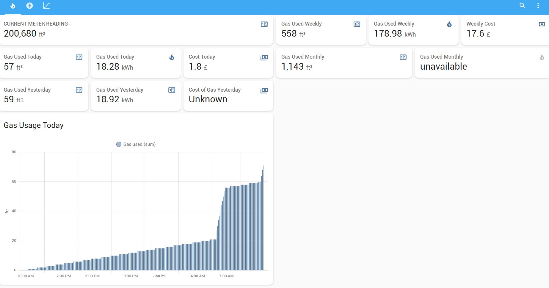
My “At A Glance” dashboard. This uses several additional ‘sensors’ I set up under the configuration.yaml as I needed to convert from ft3 to kWh and then add a cost to that kWh value. I used Meter Helpers for logging the kWh values i.e. daily, yesterday (last period), weekly, monthly and so on…
In the top corner of the dashboard is my current meter reading, and this matches exactly (except for the last two digits - these don’t get reported back to my gas company) the readings from my gas meter… it hasn’t missed any pulses, and it doesn’t receive any spurious pulses either.
This setup has now been running for about a month in its current form and has worked far better than I thought it would.
If anybody has any questions do feel free to ask. I’m more than happy to help.
