This is just for information and I’m not advising you to do anything…
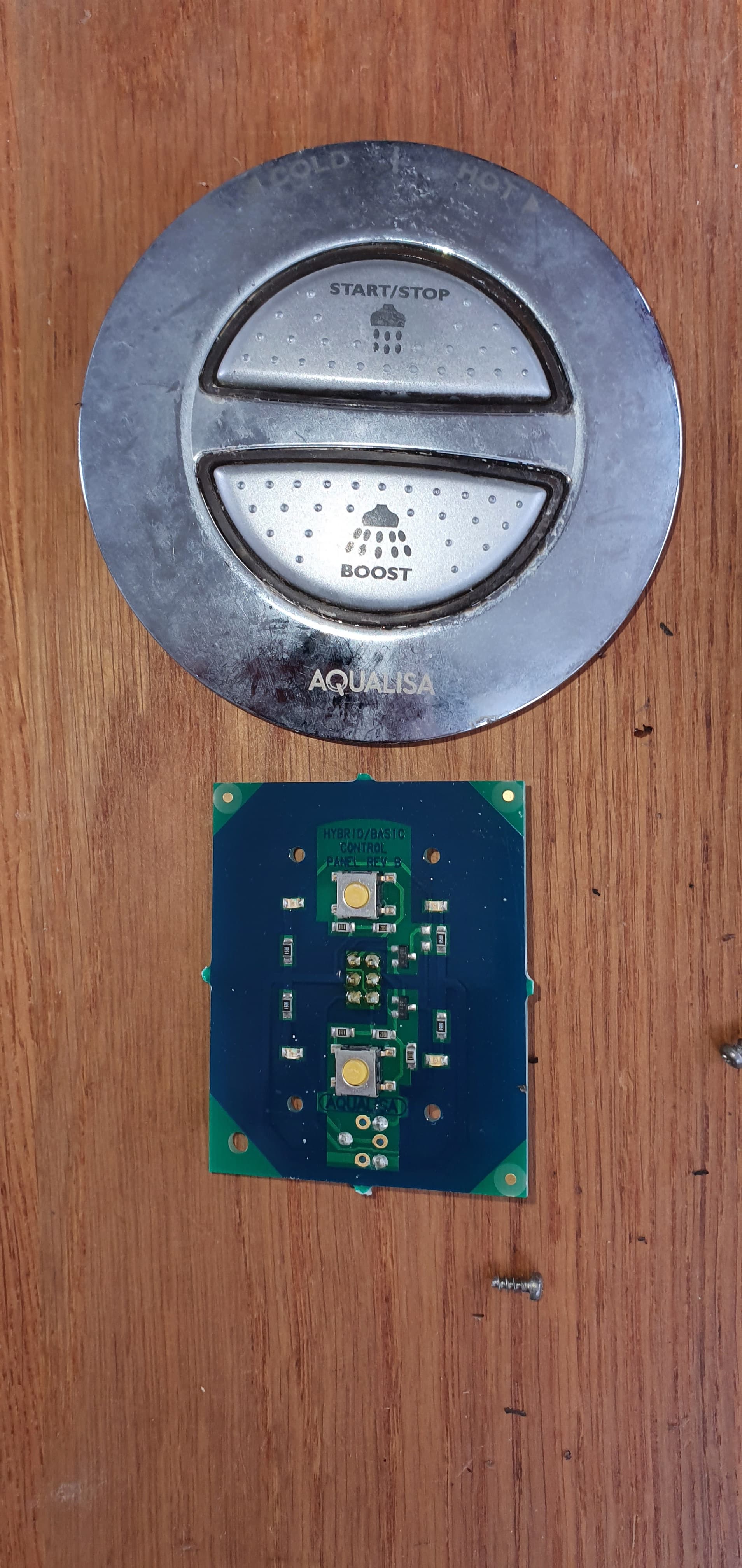
Apologies for butting in. I have an Aqualisa Quartz Blue shower with a raspberry coloured controller. The on/off is controlled by a push button and temp adjusted by turning the outer ring.
The remote switch is connected to the controller by three twisted pair cables. The controller has two ports with the wires from each port wired in parallel. By connect a second RJ12/13 to the commissioned shower, effectively, you have the makings of a break out box.
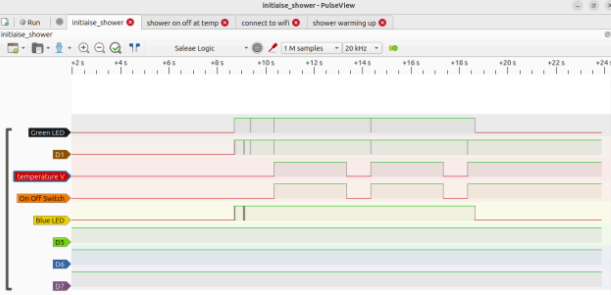
Attaching a £4 multi-channel logic analyser, you can capture the handshake of when the device powers up or the switch on or off process, which looks like this:
Using a RJ12 breakout box, the wiring seems to be:
Pin1 = Green LED - 0v to 5v
Pin2 = 5v supply from shower controller
Pin3 = Temp adjustment 0v to 5v - warm shower was at 3v2
Pin4 = On/Off signal, usually high, pulse low to signal
Pin5 = Logic ground
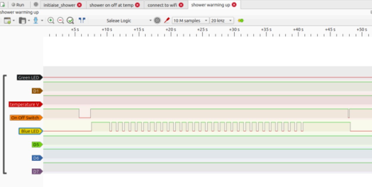
Pin6 = Blue LED - flashing means warming up, solid means warmed to preset
From the next image, you can see that pulsing pin4 to ground starts the shower and the blue LED flashes until up to temp.
So, all you have to do is replicate the behaviour with an ESP/Rpi.
I used a Raspberry Pico W (works at 5v) with ESPHome and the following .yaml
#////////////////////////////////////////////////////////////////////
esphome:
name: node-picow1
friendly_name: Node-PicoW1
#set pin high in boot
on_boot:
priority: 600
then:
- switch.turn_on: trigger_sensor
  - lambda: |-
      pinMode(6, OUTPUT);
      digitalWrite(6, HIGH);
rp2040:
board: rpipicow
Enable logging
logger:
Enable Home Assistant API
api:
encryption:
key:
ota:
- platform: esphome
password:
wifi:
ssid: !secret wifi_ssid
password: !secret wifi_password
Enable fallback hotspot in case wifi connection fails
ap:
ssid: “Node-Pico1 Fallback Hotspot”
password:
switch:
- platform: gpio
pin: GPIO4 # wired to GPIO5 so turning the shower on triggeres a pulse
name: “en Suite Shower”
id: enSuiteShower
#//////////////////////////////////////////////////
binary_sensor:
-
platform: gpio
pin: GPIO5 # GPIO5 is wired to GPIO4 - When GPIO4 changes state, this routine sends a 500ms low pulse out via GPIO6
name: “Trigger Pulse”
id: trigger_sensor
internal: True
on_state:
then:
- output.turn_off: pulseOutput
- delay: 500ms
- output.turn_on: pulseOutput
-
platform: gpio
pin:
number: GPIO15 # Look for on/off status
mode:
input: true
pulldown: true
name: “Up to Temperature ??”
id: warming_status
need to have the signal as pull down
output:
- platform: gpio
pin: GPIO6 # Where you define the pin output
id: pulseOutput
#///////////////////////////////////////////////////////////////
Take the power for the Pico from Pin2 and Ground on Pin5, connect GPIO4 to GPIO5. Take the pulsed output from GPIO6 to shower controller pin 4. GPIO15 is the incoming signal, should be wired to Pin6.
Once in ESPHome/Home Assistant, you can add voice control… which I did.
The beauty of this route is it’s self contained/powered by the shower and more over, there is no cloud based account sucking up your personal data or activity. I’m no programmer so I’m sure the code/set up could be greatly enhanced. To measure water usage, put the shower head in a bucket and measure the flow versus time, map that to the time in use.
Let me know your thoughts