I’m planning on building a new house in a year so I want to make sure I wire the home in the best way to work with HA. I want a sensor on every door, internal and external. My plan is to run wires to each door and homerun them to the basement utility room. I’m looking at using a magnetic switch like this.
I’ve heard in the past about using a DSC alarm wiring panel and being able to integrate that with HA but I haven’t seen much on that lately. I’m assuming I can use just about anything with some GPIO pins and can use MQTT, right? If I used a Node MCU with Tasmota, it looks like it would work with 10 sensors as it has 10 GPIO pins. Is my thinking correct? Is it jus a matter of grounding the GPIO pin (run one sensor wire to ground and the other to a GPIO pin?)
Is there a better way to do this that I’m not thinking about? I would probably have 30+ door sensors. I’d also like to integrate motion sensors in this way too, if possible. I’ll probably also run some wires for sirens. I’m thinking about using a 4ch Sonoff to fire those off.
I have my external doors wired into a NodeMCU one side of the reed switch to GPIO the other to ground. Loaded ESPEasy and set it to MQTT the status updates. Works like a charm.
Alternatively you could use the Konnected hardware/software to achieve this as well.
D3 and 4 need to be high at boot, and D8 needs to be low. So you may not get to use all 10 gpios.
I’ve also had problems when the switch is too far away from the ESP making the wire run too long.
An alarm panel is designed to read these switches over long wire distances, so I think they are not susceptible to this problem.
So you may be better off with more ESP’s distributed around the house. I use the wemos mini d1 version, and they might be a little cheaper.
My honeywell panel has a lot of the sensors strung in series because it doesn’t have very many zones (inputs), which is the disadvantage of alarm panels. You can add more zones, but it’s not cheap.
Since you are building the house, I would suggest wiring ethernet cable from your router to wherever your connection point is, and avoid using wifi whenever possible, purely for reliability.
I looked into Konnected and figured that would be a good option until I saw the price. $90!! It looks like it only has 6 zones, so I would need 5 boards ($450) to sense 30 doors. Am I wrong in thinking that Konnected is basically a NodeMCU or D1 Mini with screw terminals instead of GPIO pins?? Is there something more to it that I am missing?
You could design your own PCB to seat NodeMCUs and break out the pins, either way you’re limited due to the amount of doors you wish to monitor. You’ll need multiple microcontrollers to monitor 30 reed switches independently.
That’s not true, if you use the MCP23017 like I mentioned above over the I2C Bus you get an additional 16 GPIO pins. You can use 8 of these Chips with out a multiplexer which gives you a total of 128 GPIO pins.
You could also use 8 MCP23008 which use a different addressing range to the MCP23017 which would give you an additional 64 GPIO pins to the 128 from the MCP23017.
If you wanted to get really fancy you could use 8 TCA9548A I2C Multiplexer’s and have 64 MCP23017’s attached giving you 1024 GPIO pins.
There are other alternatives such as the SPI bus as well.
Just pull paired cable from each door/window you want to monitor to one central location somewhere.
Then use e.g. Arduino MEGA having a lot of I/O to build local alarm system of which interfaces to HA somehow. But does not depend on HA. As you have so many things to monitor and have a possibility to run cables at building state I would go with the cables.
Just need to ensure that the used cable does not have too much resistance. MEGA is 5V but maybe better idea would be to use 12VDC and optoisolators when reading the signal to microcontroller. To ensure reliability.
Or you could create clusters of inhouse doors and use databus to deliver info (still HW). And have all important doors directly connected. This might be bad idea if later someone wants to connect some other system but is forced to use these local clusters…
Here is a picture of my setup. A board with 2 MCP23017 (40 pins): https://www.abelectronics.co.uk/p/54/io-pi-plus. I soldered a couple of idc20 ribbon connectors to it and ordered a couple of boards with screw block terminals and idc20 connectors from china. It works like a charm.
The board with the screw block terminals goes inside the box in the wall behind the plate, with the flat ribbon cable coming out from under it. There is another whole bunch of sensor wires behind those other 2 plates that I still need to connect.
I just finished a project with the NodeMCU and the MCP23017 Port Expander. It was quite easy to make it work. The chip has three address pins, so you can interface 15 of them on two pins of the NodeMCU (GPIO4 and 5), giving you a total of 120 digital IO ports. Simply make each switch cause an MQTT state message to be generated once a minute, then set them up as sensors into Home Assistant.
On the wiring, I recommend that you buy a 1,000 ft roll of CAT5 cable and run it everywhere that you may ever need a node- even if you are only using two of eight conductors.
I’d recommend that you consider using a real alarm system. Alarm systems are stand alone and generally have bullet proof firmware if you stick with standard companies. Honeywell’s Vista series and the DSC alarms are popular choices. That gives you a real, working burglary deterrent that doesn’t depend on the internet, or having a server/pi running. Then add an alarmdecoder or envisalink to connect the alarm to HA. You don’t have to pay an alarm monitoring system - the alarmdecoder will email you (or use HA for notifications).
If you don’t want a real alarm system, another approach is to use MySensors which is a very nice arduino/esp library for connecting a variety of sensors and actuators together with low cost radios. There are MQTT gateways you can build for it and there is a HA integration that works as well.
I’m revisiting this now that I’m closer to starting my home build. I re-read all the responses and realized that basically everything you guys said is over my head. I’m very much an amateur, so the simpler the better.
I’ve been playing around with multiple reed switches on a Wemos D1 Mini. I can see in the Tasmota console that I can use more than 1 GPIO pin on the Wemos D1 to monitor more than 1 reed switch, but I can’t see how to send a different MQTT message based on which reed switch was tripped. The console message always shows:
04:34:02 MQT: stat/reed-switch-test/RESULT = {“POWER”:“ON”}
04:34:02 MQT: stat/reed-switch-test/POWER = ON
Regardless of whether my reed switch on Gnd>GPIO14 or Gnd>GPIO12 is tripped. In order to differentiate between the reed switches (doors) I need to be able to send a different MQTT message per GPIO pin that is connected to the switch, correct?
Also, I don’t really have a problem using 30 Wemos D1 Minis if need be. I just figured I might as well consolidate. If I could get 5-10 switches per Wemos D1 Mini, that would be fine with me.
Which reed switches did you use in the end? I’m looking to integrate this hopefully with esphome, but i only need one or two reed switches per wemos d1 mini.
I’m actually about 2 weeks away from pulling wires, the home is framed and the HVAC and plumbing is being roughed in right now.
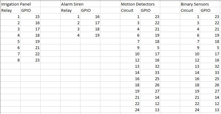
I’m going to use these contact sensors in every door. I’ll run a 22/2 wire to every door and homerun it to my mech closet. I made a few 3D printed panels with an ESP32 board and terminal block. I’ll use ESPhome to control everything.
Do you intend to run long lengths of wire with those sensors attached directly to the ESP32 GPIO pins?
At the very least you need a strong pullup resistor (4.7K) at each pin.
However you’re connecting long antennae directly to MCU pins, so you run a high risk of at the very least receiving false triggers, and more likely burning out pins or the MCU as time goes on.
I tested with 1,000 feet of 22 gauge wire, hooking one end to the ESP 32 GPIO and the other to a magnetic reed switch and it worked as intended. My longest run is probably 100 feet.
Was the wire installed, or on a spool? Short term testing might be OK. But can you simulate big electrical appliances being turned on and off, lightning strikes nearby, static electricity, , someone welding next door, etc.?
A pullup resistor will forcefully hold the ESP32 pin high at supply voltage. When your switch is activated, it grounds that pin. Is a much more reliable way to detect switch transitions because it avoids floating the pin. The internal pullups are fairly week at either 10K around 50K (don’t remember exactly).
Here’s a quick explanation of opto-isolating processor inputs:
You can also get ready-made boards with opto-isolators installed.