I did try contacting them few years ago.
Did not get answer from them. Instead - got an email from local representatives (tenko). They just sent a modbus documentation.
typical…
they seem not to care.
too bad, really. apparently their niche clientele doesnt care, or doesnt mind paying sky-high prices for Brink branded devices (sensor, modbus, even cabling).
Even their Opentherm system was closed down and now no longer can be controlled other than by a Brink thermostat?
After powerloss or reboot from the esp, the Brink goes back to Display LCD control mode.
I have programmed it, to go to Modbus Step control mode, so the modbus steps work again.
There is a test button (not essential) for easy testing.
If you are running the Brink on Modbus flow controlling, you can change the auto new_value from 1 to 2
substitutions:
  name: brink

esphome:
  name: ${name}
  on_boot:
    priority: 200
    then:
      - script.execute: on_boot

script:
###  On reboot or powerloss of the esp, set the command to Modbus Step instead of Device LCD
  - id: on_boot
    then:
      - lambda: |-
          auto new_value = 1;

          esphome::modbus_controller::ModbusController *controller = id(${name});
          auto set_value_cmd = esphome::modbus_controller::ModbusCommandItem::create_write_single_command(
            controller, 8000, new_value);

          delay(200) ;
          controller->queue_command(set_value_cmd);
          ESP_LOGI("ModbusLambda", "Brink Modbus Step set");


button:
  - id: Step_modbus
    name: Step Modbus
    platform: template
    on_press:
      then:
       - lambda: |-
           auto new_value = 1;

           esphome::modbus_controller::ModbusController *controller = id(${name});
           auto set_value_cmd = esphome::modbus_controller::ModbusCommandItem::create_write_single_command(
             controller, 8000, new_value);

           delay(200) ;
           controller->queue_command(set_value_cmd);
           ESP_LOGI("ModbusLambda", "Brink Modbus Step set");
2 Likes
@Atlantis, thank you so much for sharing this. I’ve just got a new Flair 300 and (with some help) it works great now with HA.
@Fonske, would it be possible to share your dashboard/yaml again? The previous posted link is expired. I’m impressed by what you made of it and it is more or less the same as what I am looking for to manage the WTW.
2 Likes
Thanks for sharing!
1 Like
Hi,
I have also tried to connect via modbus to Brink Flair 325 (without any extension boards), but did not succeed (yet) ![]()
Hardware used: NodeMcu Lua CP2102 (ESP8266) + MAX3485 Module TTL To RS485 Module
Adjusted config for ESP8266, based on Modbus Controller — ESPHome, used
For hardware serial only a limited set of pins can be used. Either
tx_pin: GPIO1andrx_pin: GPIO3ortx_pin: GPIO15andrx_pin: GPIO13.
Also disabled logging by setting: baud_rate: 0
After flashing and wiring to HRU, my ESP connects to Wifi, but does not receive any data…
Tried to rewire to GPIO15/13, tried to set modbus channel to 0x14 or 0x1, parity even or none.
Nothing helps…
Logs sometimes show
NFO Successfully connected to brink.local
[21:49:44][I][app:102]: ESPHome version 2023.6.5 compiled on Jul 17 2023, 21:48:54
[21:49:44][C][wifi:543]: WiFi:
[21:49:44][C][wifi:379]:   Local MAC: ######
[21:49:44][C][wifi:380]:   SSID: '#######'
[21:49:44][C][wifi:381]:   IP Address: 192.168.1.129
[21:49:44][C][wifi:382]:   BSSID: 00:1E:E5:79:A9:DF
[21:49:44][C][wifi:384]:   Hostname: 'brink'
[21:49:44][C][wifi:386]:   Signal strength: -41 dB ▂▄▆█
[21:49:44][C][wifi:390]:   Channel: 1
[21:49:44][C][wifi:391]:   Subnet: 255.255.255.0
[21:49:44][C][wifi:392]:   Gateway: 192.168.1.1
[21:49:44][C][wifi:393]:   DNS1: 192.168.1.1
[21:49:44][C][wifi:394]:   DNS2: 0.0.0.0
[21:49:44][C][logger:301]: Logger:
[21:49:44][C][logger:302]:   Level: DEBUG
[21:49:44][C][logger:303]:   Log Baud Rate: 0
[21:49:44][C][logger:305]:   Hardware UART: UART0
[21:49:44][C][uart.arduino_esp8266:102]: UART Bus:
[21:49:44][C][uart.arduino_esp8266:103]:   TX Pin: GPIO1
[21:49:44][C][uart.arduino_esp8266:104]:   RX Pin: GPIO3
[21:49:44][C][uart.arduino_esp8266:106]:   RX Buffer Size: 256
[21:49:44][C][uart.arduino_esp8266:108]:   Baud Rate: 19200 baud
[21:49:44][C][uart.arduino_esp8266:109]:   Data Bits: 8
[21:49:44][C][uart.arduino_esp8266:110]:   Parity: EVEN
[21:49:44][C][uart.arduino_esp8266:111]:   Stop bits: 1
[21:49:44][C][uart.arduino_esp8266:113]:   Using hardware serial interface.
[21:49:44][C][modbus:143]: Modbus:
[21:49:44][C][modbus:145]:   Send Wait Time: 2000 ms
[21:49:44][C][modbus:146]:   CRC Disabled: NO
[21:49:44][C][modbus_controller.sensor:010]: modbus_controller.sensorModbus Controller Sensor 'Rekup To House temperature'
[21:49:44][C][modbus_controller.sensor:010]: modbus_controller.sensor  State Class: ''
[21:49:44][C][modbus_controller.sensor:010]: modbus_controller.sensor  Unit of Measurement: '°C'
[21:49:44][C][modbus_controller.sensor:010]: modbus_controller.sensor  Accuracy Decimals: 1
[21:49:44][C][captive_portal:088]: Captive Portal:
[21:49:44][C][web_server:161]: Web Server:
[21:49:44][C][web_server:162]:   Address: brink.local:80
[21:49:44][C][mdns:112]: mDNS:
[21:49:44][C][mdns:113]:   Hostname: brink
[21:49:44][C][ota:093]: Over-The-Air Updates:
[21:49:44][C][ota:094]:   Address: brink.local:8266
[21:49:44][C][ota:097]:   Using Password.
[21:49:44][C][api:138]: API Server:
[21:49:44][C][api:139]:   Address: brink.local:6053
[21:49:44][C][api:141]:   Using noise encryption: YES
[21:49:44][C][modbus_controller:275]: ModbusController:
[21:49:44][C][modbus_controller:276]:   Address: 0x14
[21:49:47][D][modbus_controller:029]: Modbus command to device=20 register=0xFC4 countdown=0 no response received - removed from send queue
[21:50:00][D][modbus_controller:029]: Modbus command to device=20 register=0xFC4 countdown=0 no response received - removed from send queue
[21:50:15][D][modbus_controller:029]: Modbus command to device=20 register=0xFC4 countdown=0 no response received - removed from send queue
[21:50:30][D][modbus_controller:029]: Modbus command to device=20 register=0xFC4 countdown=0 no response received - removed from send queue
In some cases - just silent.
Tried to replace RS3458 with new one, same situation.
Can you give some hints where to dig?
I saw @BroutMouton had similar issues, and he posted diagram, where he wired VCC (RS485 side to 5V), is this safe?
I would not like to risk burning my new HRU ![]()
My yaml file:
esphome:
  name: brink
  friendly_name: Brink
  platform: ESP8266
  board: nodemcuv2

# Enable logging
logger:
  level: DEBUG
  baud_rate: 0  # <--- super important!

web_server:
  port: 80

# Enable Home Assistant API
api:
  encryption:
    key: "Zmij8QoVtky0BXSxIl7KZJF0DUY3JRiTQJldqpjxb9Y="

ota:
  password: "e47f2e0b8067e594c9af27218472a152"

wifi:
  networks:
  - ssid: Troliu
    password: secret

  # Enable fallback hotspot (captive portal) in case wifi connection fails
  ap:
    ssid: "Brink Fallback Hotspot"
    password: "nGZq8sl51Twc"

captive_portal:

uart:
  id: mod_bus
  rx_pin: GPIO3
  tx_pin: GPIO1
  # rx_pin: D2
  # tx_pin: D3
  baud_rate: 19200
  # data_bits: 8
  stop_bits: 1
  parity: even

modbus:
  id: modbus1
  # flow_control_pin: D0
  send_wait_time: 2000ms

modbus_controller:
  - id: rekup
    ## the Modbus device addr.
    address: 0x14
    modbus_id: modbus1
    setup_priority: -10
    update_interval: 15s

text_sensor:
  - platform: modbus_controller
    modbus_controller_id: rekup
    id: rekup_bypass_status_text
    register_type: read
    address: 4050
    raw_encode: NONE
    name: Rekup Bypass Status
    lambda: |-
      uint16_t int_mode = (data[item->offset] << 8) + data[item->offset+1];
      ESP_LOGD("main","Parsed operation mode int : %d", int_mode);
      std::string mode_str;
      switch (int_mode) {
        case 0:  mode_str = "INITIALIZATING"; break;
        case 1:  mode_str = "OPEN"; break;
        case 2:  mode_str = "CLOSED"; break;
        case 3:  mode_str = "OPEN"; break;
        case 4:  mode_str = "CLOSED"; break;
        default: mode_str = "Unknown"; break;

      }
      return mode_str;

sensor:
  - platform: modbus_controller
    modbus_controller_id: rekup
    name: "Rekup To House temperature"
    id: rekup_to_house_temp
    register_type: read
    address: 4036
    unit_of_measurement: "°C"
    value_type: S_WORD
    accuracy_decimals: 1
    filters:
      - multiply: 0.1
UPDATE: Finally it works, I have changed pins for TX and RX to D1 and D2 and it awake ![]()
uart:
  id: mod_bus
  rx_pin: D2
  tx_pin: D1
  baud_rate: 19200
  parity: even
Hello,
Is it posible to use this PCB for this?
Best regard
I believe, yes. It has ESP32 chip + RS485 outputs.
But I believe it costs 10 times more than 5$ 
I’m interested. i live in the Netherlands, Utrecht. What is your price and do you have a picture of it all?
@rieschard
Here are some pictures of V2
230V or 24 VDC (or 5 VDC through usb) power supply
esp32S3-T7 (lilygo)
modbus RTU (XY-017)
1 relais
2x i2C for sensors (m5 stack)
DHT22 or ds18b20

Still need litlle bit testing to do, received it yesterday
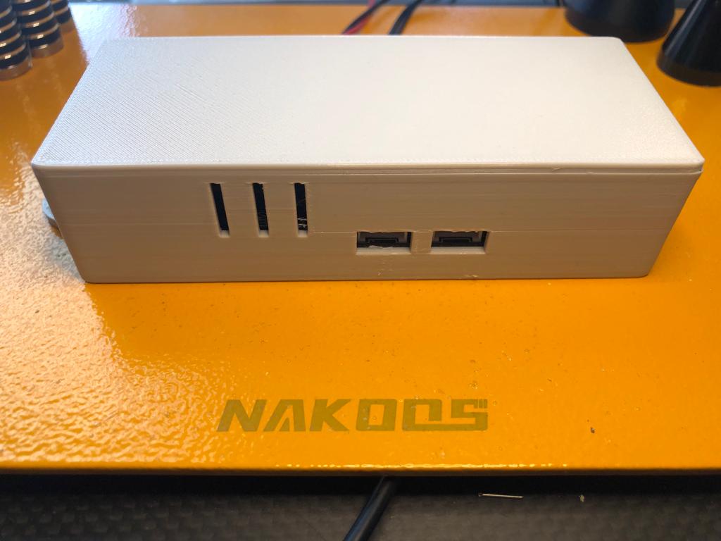
And still make a 3d printed housing design, probably tommorrow or the day after
Price will be arround 35 euro (incl transportation in netherlands), but will dependant of the power supply (230 V option adds 18 euro, but not needed for brink)
And V1
modbus RTU (XY-017)
esp32 (MH-ET-LIVE)
usb 5V

price around 25 euro (incl transportion cost inside netherlands)
With the help of Egidijus, we have translated the files to english and dutch on my github (link in the post above)
Also code suitable for esp32 and esp8266
Thanks for the photos
I am not interested in 230 v or the extra sensor.
Dont understand the function of all the connectors in v2, and v1 seems to be missing one (I thought A,B and ground)
@rieschard
The 2-terminal green block on the PCB is A+ en B-. I wanted to have it on the side instead of the top.
Gnd is not necesarry for the modbus RTU. (power levels between A en B, not A, B and GND)
V1 can be connected through usb port on front of the brink.


The Brink also has 24VDC on the terminals, thats why i made a V2.
Also Brink is missing the RH and temp from suction side from house and i wanted to have a possibillity to connect another sensor for example a SCD41 for CO2 measurement.
The relais can be used for a zone steering (valves). Just some future ideas.
Send me an email through alphonsuijtdehaag at gmail dot com if you are interested in a pcb
Edit: some pictures of V2:


I have put an advertisement now on Tweakers website for version 2
ESP32 PCB incl relais, modbus, one-wire, i2c connectoren aangeboden - Vraag & Aanbod - Tweakers
1 Like
Hello again.
Is this PCB OK to use this?
https://www.electrodragon.com/product/esp32-can-rs-485-wire-interface-shield/
Best regard
@daki1978
Thats only a shield PCB.
You might try this one:
LILYGO® TTGO T-CAN485 ESP32 CAN RS-485 from Lilygo on Tindie
Thanks @Fonske, I am running the version 2 hardware you send me for a few days now and it all works as expected. And thanks for your “after sales” support.
1 Like
Has anyone managed to switch the valve of the co2 module via modbus? so you can choose the zone of ventilation
I have added a delay to the script in my scenario:
-script:
  - id: on_boot
    then:
      - delay: 300s  # Adjust the delay time based on your needs
      - lambda: |-
          auto new_value = 2;
          ...
          ...
The reason for this is when you have a total power failure in the whole house and the power comes back, the ESP will boot up much quicker than the Brink does, meaning the script is executed, but the ventilation unit is not responding yet.
Thank you.
I have added it also to my github code.
Another note:
Currently i have connected a m5stack RS485 with an m5stack Atom S3 lite.
Power supply from Brink 24VDC to the 12V / GND connection on the m5stack.
It has a wider range of DC power supply, it won’t give any problems.
Also it has an i2C connector, so SCD41 or ENVIII is also possible (missing values on the inlet brink from suction side house.
2 Likes
Hi there. Great work you have here!
Question If I understood well this latest setup you have - you used the 24v supply from brink terminal to power the m5stack on the Atomic rs485 base which then is connected/suplies the Atmom s3 lite? No need for 12v supply or DC-DC down step?
Thanks in advance!