I have just setup the same for use in HA, however im having a couple of problems that i hope someone can help with?
There is 5 sections of 3 LEDs +ICs powered from the head end of the strip all lights good brightness etc.
I have set the arduino code as the same as the tutorial colour order BRG.- Not sure if this is right for my LEDs
The Colour selection doesnt match the colours shown on the LEDs and it doesnt alwayts change the full strip of 5 sections.
The LEDs when switt randomly depependednt on what colour is illuminated, ie all LEDs may not turn off, groups will stay on or sometimes they do go off.
The effects drop down box is shown in Grey with no options listed.
The automation code, is invalid config when restarting HA.
This section of arduino code #define NUM_LEDS 186 ------ Do i need to modify this? #define DATA_PIN 5 ---- Data Pin is correct pin
//#define CLOCK_PIN 5 #define CHIPSET WS2811 - Not sure on chipset any thoughts? #define COLOR_ORDER BRG - Again i dont think this is quite correct for my LEDs??
If you could give me some pointers i would be really grateful.
NUM_LEDS - yes, that has to match the number of LEDs CHIPSET - you didn’t tell us what LED strip you bought, so nobody can answer that
As for colour order, the simplest approach is probably to set the strip to all blue, then all red, then all green. That way you know what the order really is.
sorry i just copied and pasted the code. Ive since checked the chipset and confirmed as the same. I will update the number of LEDs in my esp code and try that. Would this have a knock on effect with isssues 3/4 do you know?
No idea about 3 as I’ve not used it (a project for later this year hopefully). Hard to know about 4 though, since again you haven’t provided details. See https://home-assistant.io/docs/configuration/troubleshooting/ for how to troubleshoot - the output of the check config command would help people a lot.
Hey People i was also struggling bit more with the hardware part. Once I fixed everything up it used to work but when I had to change a cable or replace a cable or the level shifter it broke and no lights nothing I will rebuild from scratch again and let u know. I also found another code. Might be interning also https://github.com/Snipercaine/Holiday-LED-files/blob/master/OutsideLEDs_Public.ino
Well the issue I have at the moment is that the leds (5meters 300 leds) turn on/off very randomly and not at all reacting to the command given from Home assistant.
Even turn Off doesn’t work as many leds stay on.
Colors are all random. Effects also random.
I blew up 1 wemos d1 mini because I accidentally put the output + and - wires on the wemos d1. Very stupid mistake of course because it blew up my wemos!
So my question first is: May this have caused the leds to now work so randomly?
I also had some fastlib error codes when uploading the sketch. How can I test that the led strip is still 100% ok?
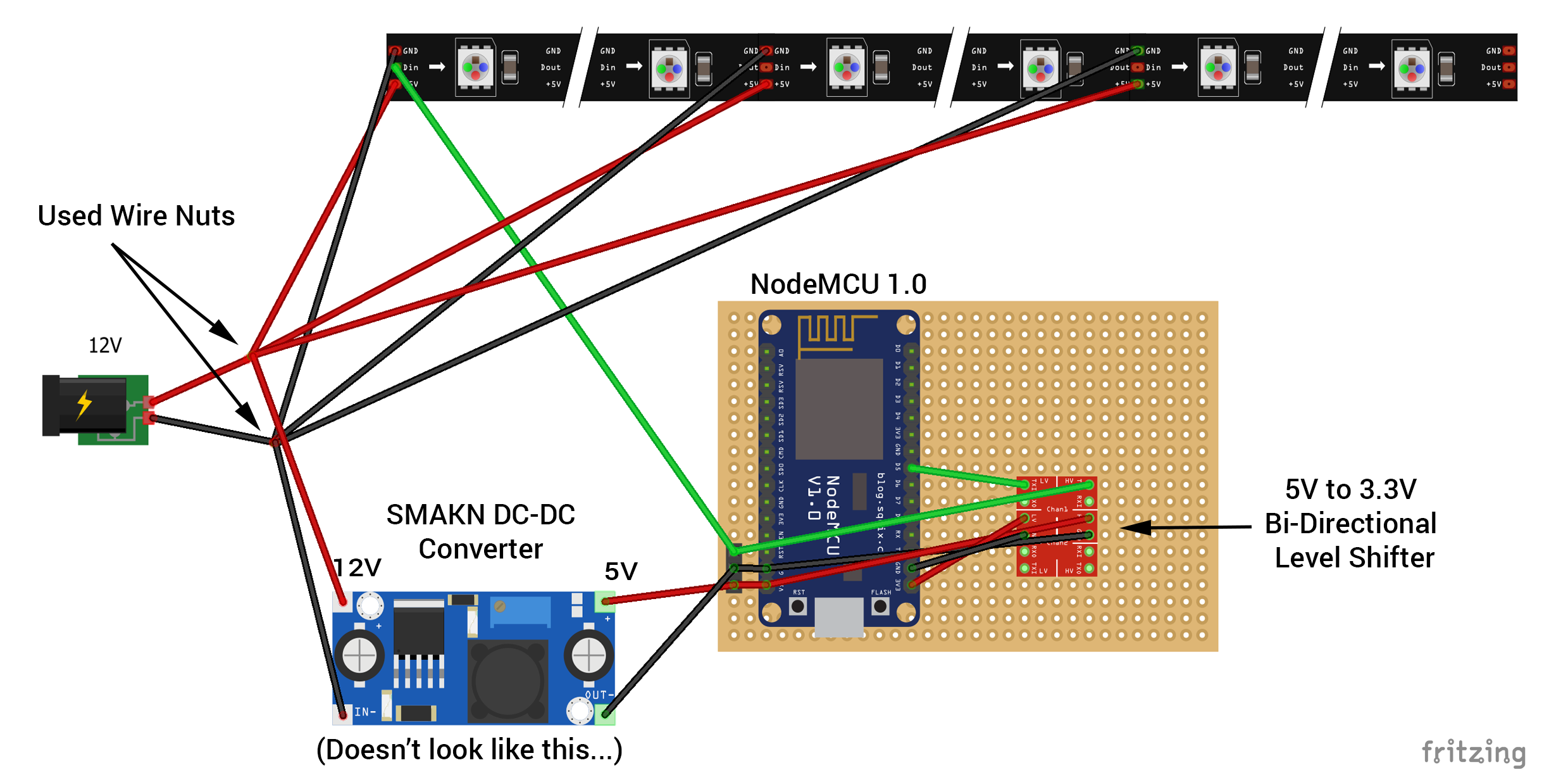
Firstly we would have to know what kind of LED strip you are using. Some are 5v and some are 12v and this changes the whole wiring diagram. Assuming you are using ws2812b (they are the most common, aka neopixels)
I have found that the Wemos boards (although capable) start to get buggy running around 64 LEDs without an external power source (the black connector.) For 300 LEDs you will definitely need an external power source to run the LEDS. I’ve found that is you are using ws2812b, aka neopixels, 300 leds will draw almost 5 amps at max brightness in solid white.
To simplify the wiring I would suggest at least a 5v 5+amp power supply. This would be able to power both the Wemos and the LEDS. They need to share a unified ground and you will probably have to run 2 power leads from the brick to the LEDS themselves. You can run POWER and GROUND lines to the In and Out of the strip, this will make your colors even across the 300 LEDS. The Data line, Din just needs a single lead going to the first LED. Since you are using a 5v capable wemos board your wiring is much more similar to an arduino and a great guide is on the Adafruit site https://learn.adafruit.com/adafruit-neopixel-uberguide/basic-connections. As the picture shows you don’t necessarily need usb power from the pc, you can use the same power supply to run the LEDS as the Wemos.
I hope that clears things up a bit, I’m running the Bruh Automation guide myself and noticed a bit of flickering in the strip, and that was cleared up by adding “#define FASTLED_ALLOW_INTERRUPTS 0” without the quotes to the line above #include <FastLED.h> in the sketch. Also if you are using ws2812b leds make sure to change the fastled definitions to #define CHIPSET WS2811 #define COLOR_ORDER GRB
after you put in your led count and define the pin. Lines 69-73. You can leave the chipset as ws2811.
I actually have WS2811 leds, so 12V leds, and externally power them with a 12V 10A powersupply.
So I guess at least half of the strip (which would be around 2,5 meter) should work fine.
I don’t think I need the capacitor or resistance thingy I see in the picture on the url you shared, right?
I’m powering the Wemos (like all my Wemos devices) using a usb adapter (so not from the pc). But of course I can look later on at powering the Wemos from the 12V (together with the 12v to 5v converter) adapter.
My main concern at the moment is how to know if something is wrong with the led strip (as the leds are freaking out. I’ll maybe make a video), or if something is wrong with something else.
I already have this shifter at home but not sure how to connect it. As I said the example image is not very clear to me.
As I’m powering (at least for now) the Wemos separately, can I just directly connect the + and - from the converter to the shifter so without connecting it with the Wemos (either when going to the shifter or going back from the shifter)?
And can I directly connect the data wire from the strip to the shifter, and then from the shifter to the wemos?
So something like this: http://imageshack.com/i/pmh1izDCp ?
What about the messages I see when compiling the sketch: https://pastebin.com/wB5g713L
Are they errors? Or things I can ignore?
Thanks for your help. I have everything in house and would like to get this done and working.
Sorry I am not very experienced in 12v LED strips, I went right for the 5v models because of their simpler power scheme.
With the 5v LED strips the capacitor is to protect the LED strip from being damaged by the power source, not completely necessary but just for protection. The resistor is not required with a level shifter, but without one it will protect your wemos from spikes in the 5v line.
I’d probably refer to someone a bit more familiar with the 12v strips for definite answers. Looks to me like the level shifter is for the data line which is really applies to the Nodemcu pictured (not wemos) since those can not handle 5v and only output 3.3v. So to prevent damage to the data pin. I’ve had no problem with the Wemos mini handling 5v so I don’t think that is necessary. If you are getting flashes and stuttering in the animations I’d suggest the edit to the sketch I mentioned #define FASTLED_ALLOW_INTERRUPTS 0 because that resolved inconsistent patterns for me with that sketch.
I may be wrong but all the addressable strips I’ve worked with have had a unified power and grounding with the board (wemos.) I’d think you can just run the ground and power from the strip to the converter and from there to the wemos. As far as testing the strip the easiest way is to load the Fastled strandtest.ino example which comes with the library. It helps isolate issues.
So just to be a bit clear, the images you provided both show a 5v strip, and I was assuming based on 5v on the data line. If it is more than 5v that is to much for a Wemos and would at bare minimum need the dc converter to bring it to 5v.
If the sketch uploads and the LEDS are being controlled I wouldn’t worry about the SPI message, but you can always copy/paste that to google to see if its a concern.
Sorry if this is all a bit confusing I have been checking this between tasks at work and haven’t had time to do any additional research for your answers.
Yeah I already put that allow interrupts rule in the sketch but didn’t change anything.
I ran the test led a few times now and I have no idea why but the strip is now not working at all anymore. I’m now more convinced that the strip is not OK, probably form the time that I also blew up the Wemos.
So I ordered a new strip and will further test with that. Will take a few weeks before it’s here so you’ll probably hear from me again then.
Thanks for helping out, even between other tasks
It’s a pity Ben is away from internet as it appears. He build it exactly with everything I ordered (except for the nodemcu being a Wemos in my case), so he could probably help me best.
I have a 10a old PSU laptop adapter running 5M fine
How far from your led strip is the nodemcu/wemos? i.e. how long is the data cable between it and the leds? I had the same issue when mine was 2-3m… it needs to be short.
This is known to cause issues and is documented on Ben’s github
/#define FASTLED_ALLOW_INTERRUPTS 0
use this instead #define FASTLED_INTERRUPT_RETRY_COUNT 0
If you are powering the strip from 12v and the wemos/nodemcu from usb you are likely running into the same issue I was, which is that they must share a ground. Once I grounded my nodemcu to the power supply all the random flickering/non-response went away and it worked correctly.
Still, after receiving a new strip today, I know for sure now the other strip is broken. Only first 3 leds are working no matter what I do.
The new strip works great!
So currently I just use:
12V power for the strip only connected at the start of the strip (5meter 300 leds)
wemos d1 mini to control the leds
ground of 12V strip also connected to the ground of the wemos
So no levelshifters or in between powering of the strip (yet).
2 questions about the effects.
The lightning effect never seems to start pas +/- 130leds (I have 300). Other effects that sometimes start further down the strip or even at the end, work fine. So it’s maybe the delay in the lightning that is too small?
Does it work in different places of the strip as well for you guys?
I’m looking for a kind of smooth and slow color palette changing effect. Like the Mood Blobs effects for Hyperion.
Does anyone know how I can achieve that? I played around with all current effect but none are like that.
The noise + below 30 is nice indeed. I still prefer a color area for the blobs, like only warm yellow/red/orange colors and not blue/gree/purple.
But probably I need to build such an effect myself.


