This is my second attempt at flashing a device with ESPHome. The first one used a TYWE2S module, and I was able to flash it easily by taping each wire in place—no soldering needed. It was a piece of cake. I’m using a CH347 programmer and it looks like it supplies 3.3V correctly, and I’m trying to use web.esphome.io, ltchiptool and ESPHome Builder in Home Assistant.
This time, the CB2S is giving me a headache. I tried flashing it without desoldering the module from the smart plug, but no matter what I did to force it into flash mode, it wouldn’t work. So I went all-in: I removed the module from the smart plug and soldered each wire for a more reliable connection.
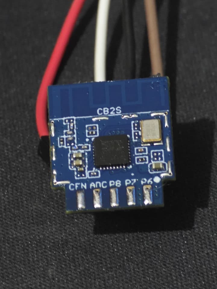
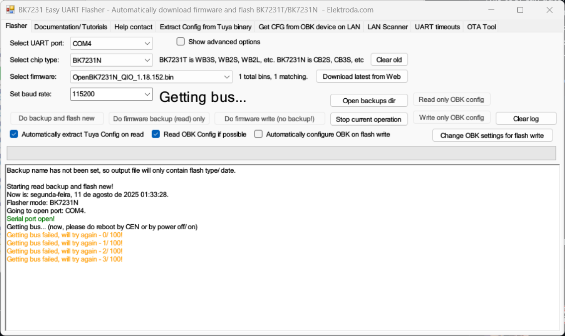
I have GND, 3.3 V, TX1, and RX1 soldered on the other side of the module with one wire per pin, as shown in the image below. I also connected a wire to the CFN pad, which appears to be the CEN pin (the one that should be shorted to GND to enter flash mode), but it still won’t work no matter what I try. One difference I noticed compared to other boards online is that mine doesn’t have the metal RF shield, though I’m not sure if that matters.
The pin is CFN, as the photo I have attached above.
The manufacturers website doesn’t show this exactly model, so I’m unsure how to put it in flash mode.
In some guides it tells you to use the CEN pin, but this pin doesn’t exist in the CB2S chip I own.
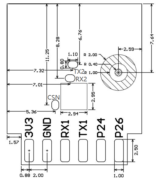
Sorry for not showing the full board, it’s late at night now and I already got the cables soldered on the 3.3V, GND, TX1 and RX1. But I can assure you the pins down there where the cables are, they’re exacty like the image schematic above. But if you want, tomorrow I can desolder everything and attach a new photo here.
The CSN pad in the middle of the board doesn’t come out to the edge connector. Be extremely careful if tempted to solder to it, as it can lift from the board and your board is stuffed. Ask me how I know…
Depending on how many times you need the serial adapter to flash the device, building a 3D printed adapter with pogo pins may be overkill for a one-off flash that then enables OTA updates from then on. Your needs are different from everybody elses. Some people get a helper to hold a wire to the pad, some hold it on with Plasticine (modelling clay) or BluTack, and others just carefully solder a very thin wire to it and cross their fingers. If you have WireWrap wire in your toolbox, it is ideal for this, but make sure to only apply the soldering iron for a very short period to prevent the pad from lifting.
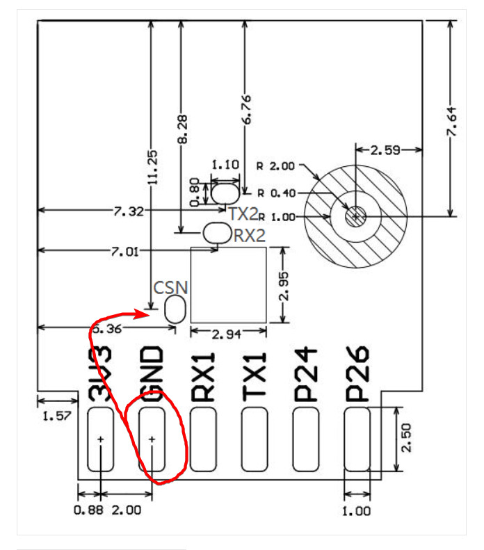
Wait a second… So instead of using the CFN connector in the front of the board, I should actually short circuit the CSN from the back to the GND?
I can easily touch a cable there while holding into the GND.
Does your CH347 programmer have enough current to power the board from the USB port? Most are right at the limit. I added a seperate 3.3v voltage regulator and two capacitors to my serial adapter for the power supply in/out pins and it has been very stable since.
It didn’t work. Same problem, I can’t get the chip into flash mode.
What I’m doing:
Plug my CH347 with all the cables in place. Start the flash and then disconnect the 3.3V cable from CH347 and plug it back (as per instruction from the software). No luck
Some boards have inbuilt pullup and pulldown resistors to help with integration. Follow the manufacturers guidelines and don’t mix up your CFN and CSN connectors as they perform different functions. All the data in the data sheet is there for a reason, even the columns to the right for tables…
From memory, your device needs the CSN pin to be grounded/low at power up to put it into programming mode.
In a hobby scene, loose wires held by hand, attempting a flash over and over till it works is acceptable. On a production line, reliable contacts such as a wiring jig with pogo pins is a must.
Best of luck with it.
But that’s the thing, CFN is not even in the data sheet
But now I’ll try with CSN, since this is the pin needed to “enter the firmware test mode”.
It’s only 1 smart plug. It’s for personal use, not a production line.
Today at morning I’ll try again, this time I’ll solder the wires in a better position, so I can handle everything and still get access to the CSN pin.
Thank you very much.
I’ll bring you guys the news
Just one question: Would I be able to flash ESPHome into this chip? Or do I need to flash that OpenBK?
I ask you this because this user even made a guide with the same chip as mine, and he flashed ESPHome into his CB2S chip
Well, I was able to flash “TYWE2S” without any problem, and it also requires 3.3V. I’ll also try to measure again with a multimeter and check if it stays at 3.3V
CEN - my typo. How embarassing! Yes, RTFM - carefully. Open mouth, insert foot, post internationally! Blushes deeply.
ESPHome has supported BK chips for a while now. Isn’t OpenBk similar to Tasmota? As long as your pin definitions are correct in your configuration, it should work with either…
The power supply internal to the CH347 chip serial adapter may not supply enough current for your programming needs, so a 0.1uF capacitor at the input and a 100uF capacitor on the output of an external 5v to 3.3v regulator chip with a suitable heatsink rated for about an amp can make up for any short spikes in demand, and you have a robust programmer for other duties as well. Add a switch to go between 3.3v and 5v, and you ahould be able to point it at most chips with the right driver aoftware to program them.
Yeah, I measure the voltage between 3.3V and GND in my CH347 and it was delivering 3.299V. That might be the problem
I have a CH341A, which is delivering 3.345V. Would that be okay?
I guess so, based on the data sheet: “* Working voltage: 3.0 to 3.6V”
I’m not a skilled guy with this things… capacitors, transistors, etc.
I’m a mere PC guy, lol.
EDIT—
Well… although the CH341A drivers are installed in my PC, my Windows refuses to detect it =x
As the data sheet shows, any voltage in the 3v to 3.6v range should be ok. Heck - some ham-fisted amateurs even drive the pins at 5 volts, often successfully, sometimes fatally releasing the minute but finite dose of inbuilt ingredient called smoke…
It is the current draw that can be an issue, where small spikes can result in device brownout or data corruption if there is not enough. The added capacitors store charge that can supply just enough oomph to ride through those small shortages, and prevent spikes on the power supply rails. Standard USB 2 ports are rated for about 500mA at 5 volts, and some ESP devices can draw 380mA when the WiFi turns on. Add that to the power draw for the CH341A serial adapter in programming mode, and you are hard up against the 500mA limit for short peaks.
CH341A Driver: In your Windoze search field on the start menu, type in device manager to pull up the old style Windows 7 device manager, turn on show hidden devices in the menu at the top, and look for any devices that have a yellow error indicator. You could find your CH341A in the serial ports section, but there may be more elsewhere. Delete/remove any yellow flagged ones and then scan for new devices or shut down cleanly to full power off and restart, and they should re-appear as part of the Plug-and-Play (also known as Plug-and-Pray) functionality introduced decades ago. Your system error log will then provide relevant information as to the cause if errors persist.
The magic smoke, I’m aware of it. I’ve seen it many times, luckly not in my hands.
Wouldn’t at least the chip go into flash mode and the software detect it? My issue here is not even a bad flash, but the lack of even starting it.
I don’t think the current draw right now is the problem. Voltage-wise it seems to be between the required voltage that the chip needs. At least with my CH347 that I know is working as expected. This CH341A I think is DOA, since I’ve never been able to use it, I bought it to flash an old TV receiver that got a bad OTA, but I couldn’t make it to work. I should probably recycle it so I don’t have to deal with it anymore xD.
Also the CH347 draws 55mA~65mA, so 380+65 = 445mA. It should still have some headroom.
Hehe, as I said, I’m a PC guy. At least this part I’ve done a couple times.
Plug and Play wouldn’t work with this guy, since it requires the wch-ic driver (manufacturer), and it also isn’t in the windows update, probably because it’s a chinese company. But at least the CH347 I’m sure it’s working, because I’ve used it to flash the TYWE2S chip with it.
445mA plus a couple of LEDs turning on and flashing during programming, drawing up to 20mA each, and you are sailing right up there at the upper limit.
If you have used the CH341A/347 successfully before, the drivers should still be on your system. Remove the yellow flagged ones and download the latest drivers from the manufacturer website, install them, do an orderly shut-down to update the registry properly, and a cold start, and try again. Often there are bug fixes, and due to export/language difficulties, they never reach the Windows HQL ecosphere for updates. Avoid drivers supplied by the sellers of your serial adapter - they never keep up to date - just forever supply ones that worked once, and never update them. They have made their eight cents profit off you already selling the cheap/cloned hardware and have no interest in spending their time hand-holding you, especially if Chinese is not your native language and you purchased only one device. All understandable in this fast paced world of dog-eat-dog and very slim margins.
Well, the only one I have was the CH347, 3 days ago, so I’m sure it’s working.
I think I’m gonna give up this CB2S chip…
I might try to buy a drop-in replacement from AliExpress so I don’t have to deal with it. As long as the pins are in the same place, I think it should be as easy as soldering the new one in the same place, right?
Remind me how much the device you purloined the CB2S chip from cost? Not just money, but time? Can you use something like CloudCutter on it, bypassing any soldering activity altogether?