Hi guys, first post, long time lurker.
Thank you all for your amazing community, that helped me many times.
Quick question.
Bought an rgb led strip + controller + ir remote from amazon.
It’s an ESP8285 based led controller, but is not flux led compatible (tried to use flux_led autodiscovery features, no result.)
It use the famous Ewelink app.
Does someone know how to integrate in home assistant?
Tomorrow i will try to flash Tasmota and play with it , but if someone know more, please help me.
Thank you.

Ok, after first look, this module use another mcu other than Esp8285.
It’s a nuvoton n76e003, and i think it’s responsible to drive the Led strip.
It’s like ESP communicate with N76e003 with some sort of command (AT commands, maybe?) and drive it.
Flashed Tasmota, any combination of GPIO in PWM mode doesn’t works. And after all, the remote is still working with tasmota firmware in ESP.
Still trying to understand.
Did you ever make any progress with this controller? I have come across the same.
It can see the Nuvoton N76E003AT20 is connected to the ESP hardware serial.
ESP p25 (RX) -> Nuvoton p2 (TX)
ESP p26 (TX) -> Nuvoton p3 (RX)
I picked one of these up and unfortunately discovered as you did that it uses a secondary MCU to control the outputs (wish I saw your post before I ordered). Since mine still has the stock FW, it should be possible to put a logic analyzer on the signals between the two MCUs and see if the comm can be decoded. I’m questioning though rather it’s worth the effort as the magic home controller, which is already usable with tasmota, only costs a couple dollars more than this one. If one was buying hundreds of them, the savings may be worth the trouble to figure out the protocol between the esp8285 and the n76e003 and come up with a solution, but I only need a couple.
I may look into it a little further, but it’s not worth putting too much effort in.
Had some luck listening to the ESP output, discovered the controller has a mic for sound reactive mode!
You were right, it is AT commands, @ baud 19200.
- ESP sends
AT+UPDATE=... - Nuvo sends back full state eg.
AT+UPDATE="switch":"on","light_type":1,"colorR":255,"colorG":0,"colorB":0,"bright":100,"mode":1,"speed":71,"sensitive":3 - ESP sends
AT+SEND=ok
Using the remote we just see the report back from Nuvo (2) and the confirmation (3), therefore the app keeps track of the state when update using the IR remote.
I have now flashed tasmota and can issue
Baudrate 19200 then SerialSend AT+UPDATE="sequence":"1554665120087","switch":"on" to get a response. I have been able to switch on/off, change colours and brightness. I do not seem to need to handle the responses to have control, only will when I need state feedback.
The sequence value in the UPDATE command sent by the ESP is the unix time value. Just consitently using “1” seems to work though.
Data dump below
Summary
On/off
AT+UPDATE="sequence":"1554665120087","switch":"on"
Set color:
AT+UPDATE="sequence":"1554661797561","mode":1,"colorR":74,"colorB":0,"colorG":255,"light_type":1
Set brightness:
AT+UPDATE="sequence":"1554662013447","mode":1,"bright":100
Set mode:
AT+UPDATE="sequence":"1554662461694","mode":1,"switch":"on"
It seems that color/speed/sensitivity can be sent at the same time as the mode (i.e. no need to change mode first)
Modes
1  Colorful (static color)
2  Colorful Gradient
3  Colorful Breath
4  DIY Gradient (fade in and out) [Speed 1- 100, color]
5  DIY Pulse  (faster fade in and out) [Speed 1- 100, color]
6  DIY Breath (toggle on/off) [Speed 1- 100, color]
7  DIY Strobe (faster toggle on/off) [Speed 1- 100, color]
8  RGB Gradient
9  RGB Pulse
10 RGB Breath
11 RGB strobe
12 Sync to music (Reacts to on board mic)  [Speed 1- 100, sensitivity 1 - 10]
Set color (in mode 5 in this example)
AT+UPDATE="sequence":"1554663306706","mode":5,"colorR":2,"colorG":0,"colorB":255,"light_type":1,"switch":"on"
Set speed (in mode 5 in this example) values 1 - 100
AT+UPDATE="sequence":"1554663227094","speed":32,"mode":5
Set sensitivity in mode 12 (sound reactive mode), values 1 - 10
AT+UPDATE="sequence":"1554663400526","mode":12,"sensitive":5
Basic mqtt config, lacking state feedback
- platform: mqtt
  name: 'RGB strip'
  command_topic: 'cmnd/rgbstrip/serialsend'
  payload_on: 'AT+UPDATE="sequence":"1","switch":"on"'
  payload_off: 'AT+UPDATE="sequence":"1","switch":"off"'
  rgb: true
  rgb_command_topic: 'cmnd/rgbstrip/serialsend'
  rgb_command_template: 'AT+UPDATE="sequence":"1","mode":1,"colorR":{{red}},"colorG":{{green}},"colorB":{{blue}},"light_type":1,"switch":"on"'
  optimistic: true
I think I need to use tasmota rules to handle incoming serial data and publish to MQTT for the state feedback?
Guess I should have come back here sooner as @reef-actor beat me to it.
I also connected up a analyzer and saw the same. A few other notes… Comm is at 19200/8N1. All transmissions both direction are terminated with ESC.
I think the responses back from the 8051 to the esp8285 are mostly to send a confirmation to the cloud. For some reason the esp also confirms to the 8051 rather messages got to the cloud, don’t know why it would care and expect it’s ignored (esp sends “AT+SEND=fail” or “AT+SEND=ok”).
All commands issued from the IR remote are sent to the esp with full information, such as:
AT+UPDATE=“switch”:“on”,“light_type”:1,“colorR”:0,“colorG”:255,“colorB”:0,“bright”:100,“mode”:3,“speed”:50
I don’t know if my board has the ability to sync to music. I didn’t see “sensitivity” in any of the messages either direction and didn’t notice anything resembling a microphone so there may be variants of the board or else I need to somehow enable this(?).
Thanks for looking into a basic tasmota config using mqtt. I’ll try it out later after I put on tasmota. If there is anything else that needs to be examined on the protocol before I kill the OEM FW let me know soon and I can test it.
FYI, this device is a variant of the Sonoff L1 RGB controller if that was already apparent. Not sure why they don’t just list it as such on Amazon.
If you still have the OEM FW, could you check the brightness values? I set a brightness value of 100 and it dimmed it to off… Could well have been user error though.
When I get a chance I will get a picture of the top of the board. I wouldn’t be surprised if there are a number of variations, knock-offs of knock-offs. I did notice there were traces for two further channels (unpopulated), so this probably also has RGBW/RGBWW variants floating around.
Other than the music sync mode, do your modes match my findings?
I still have the OEM FW and I’ll double check the brightness later today, but I’m pretty sure I saw the esp send a message with the value of 100 when I changed it from low to full brightness. Mine also has unpopulated traces for two other channels, it looks like it would need two resistors and a transistor for each additional channel.
Other than the music sync mode, my findings were the same as yours. If you hold the power button on the IR remote for 5s, it tells the esp to load factory defaults and go into pairing mode by sending: AT+SETTING=enterESPTOUCH[1B]
Not that we would care for tasmota, but just another thing I observed.
I was surprised how simple it was to decode and that they used inefficient descriptive ASCII text messages.
@reef-actor, the brightness range is 10 (dim) to 100 (full on), regardless if the change is initiated from the app/cloud side or from the IR remote. I’ll hold off a day or two on changing the FW in case there are any other things that need to be checked out.
I’'l be curious to see what your board looks like and if it has an obvious microphone.
I suppose we could use the AT+SETTING command for some other function, such as send an MQTT message to trigger an automation. I was also surprised at the comunication method, in english as well!
My module looks like the one in this tamota issue.
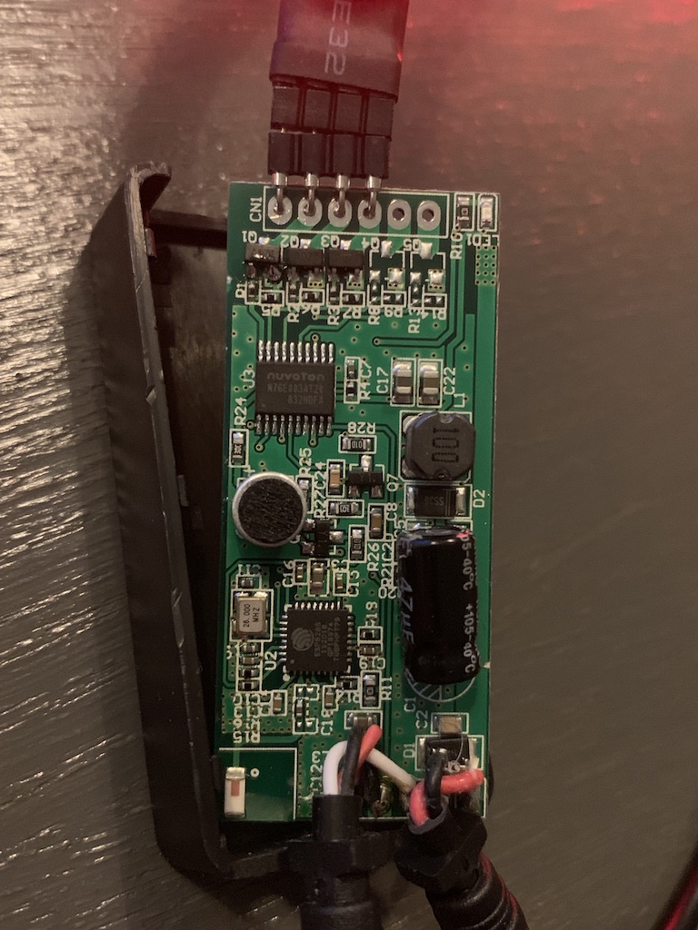
Do you have the round component between the two mircos? I think that may be the mic but I haven’t had a close look.


My code is 2018 something
i have the same exact board did you manage to flash it with tasmota and get it working it seems that it’s not working for me at all i was able to hold GPIO0 to ground and get it ready as the blue indicate stops flashing when i connect it to the power adapter but when i try to flash it fails and when i connect it to 3.3v it’s not working at all
I’m experiencing exactly the same. I’ve connected GPIO0 to Ground, and I can see the board booting up (noise on the serial port), the blue blinking light remains off (as the Sonoff firmware doesn’t boot), but no joy with esptool unfortunately.

My version is the version with 20181008 on the back of the PCB.
A good hint to be able to flash this chip would be much appreciated!
I realize that the topic is so old but I had the same situation and issue with programming ESP by serial.
The reason of that is easy: additional MCU is connected to the same RX/TX lines. So, if anybody want to use serial programming method (e.g. for recovery) needs to cut lines between ESP and MCU.
Just one more hint… my device is capable to flash by tuya-convert by on-air and any wiring is not necessary. It might work for other TuyaRGB(W) drivers as well.
Regards,
PanciO
For those who are interested, Nuvoton has an updated datasheet here:
https://www.nuvoton.com/export/resource-files/DS_N76E003_EN_Rev1.09.pdf
Hello,
I have a similar device, only with an ESP8266EX instead and the microphone for music sync as well.
I successfully flashed it with Tasmota, but I do not see anything coming in on Serial or the Nuvoton chip accepting anything by serial.
I tried all baudrates from 2400 to 115200 but I don’t see anything in the Tasmota console.
Can anyone provide some guidance here?
I have the same issue. Anything new on your side?