Connect 10 Pool Controller Protocol Documentation
This document describes the proprietary serial protocol used by the Astral Connect 10 pool controller and has been clean-room developed by sniffing the messages on the RS-232 like bus that is used for communications.
Message Structure
All messages follow this basic structure:
[START] [SRC_HI] [SRC_LO] [DST_HI] [DST_LO] [CTRL_HI] [CTRL_LO] [CMD] [SUBCMD] [DATA...] [CHECKSUM] [END]
Message Format
| Offset |
Field |
Description |
| 0 |
START |
Always 0x02 |
| 1-2 |
SOURCE |
Source device address (big endian) |
| 3-4 |
DEST |
Destination device address (big endian) |
| 5-6 |
CONTROL |
Control bytes (typically 0x80 0x00) |
| 7+ |
COMMAND |
Command and subcommand bytes |
| 10+ |
DATA |
Payload data (varies by message type) |
| N-2 |
CHECKSUM |
Sum of all data bytes (from index 10 to N-3) masked with 0xFF |
| N-1 |
END |
Always 0x03 |
Checksum Calculation
The checksum is calculated as the sum of all bytes from index 10 to (length - 3), masked to 8 bits:
uint32_t sum = 0;
for (int i = 10; i < len - 2; i++) {
    sum += data[i];
}
uint8_t checksum = sum & 0xFF;
Device Addresses
| Address |
Device |
Description |
0x0050 |
Touch Screen |
Touch screen interface. |
0x0062 |
Temp Sensor |
Temperature sensor module |
0x006F |
Controller |
Main pool controller (Connect 10) |
0x0090 |
Chlorinator |
Chemistry/chlorinator module |
0x00F0 |
Internet GW |
Internet gateway module |
0xFFFF |
Broadcast |
Broadcast to all devices |
Message Types
The messages that are fully decoded have a  and the partially decoded ones have a
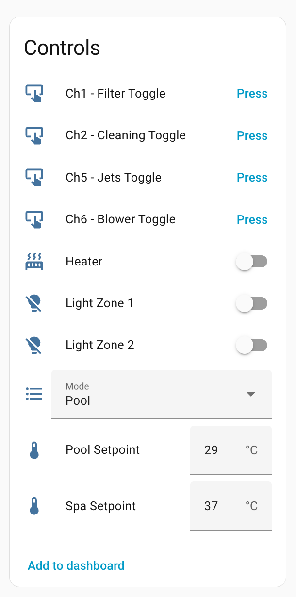
1. Mode Message (Spa/Pool)
Reports the current operating mode - pool or spa.
Pattern: 02 00 50 FF FF 80 00 14 0D F1
Example - Spa Mode:
02 00 50 FF FF 80 00 14 0D F1 00 00 03
                              ^^
                              Mode: 0x00 = Spa, 0x01 = Pool
Example - Pool Mode:
02 00 50 FF FF 80 00 14 0D F1 01 01 03
Data Fields:
- Byte 10: Mode (
0x00 = Spa, 0x01 = Pool)
2. Temperature Settings
Reports the temperature setpoints for both spa and pool.
Pattern: 02 00 50 FF FF 80 00 17 10 F7
Example:
02 00 50 FF FF 80 00 17 10 F7 25 1D 63 54 F9 03
                              ^^ Spa setpoint Celcius (37°C in this example)
                                 ^^ Pool setpoint Celcius (25°C in this example)
                                    ^^ Spa setpoint Fahrenheit (99°F in this example)
                                       ^^ Pool setpoint Fahrenheit (84°F in this example)
Data Fields:
- Byte 10: Spa setpoint temperature Celcius
- Byte 11: Pool setpoint temperature Celcius
- Byte 12: Spa setpoint temperature Fahrenheit
- Byte 13: Pool setpoint temperature Fahrenheit
Note: Temperature scale (Celsius/Fahrenheit) is set by configuration message.
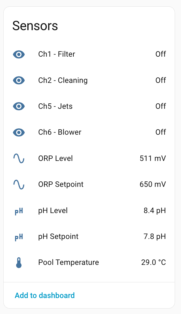
3. Temperature Reading
Current water temperature from the sensor.
Pattern: 02 00 62 FF FF 80 00 16 0E 06
Example:
02 00 62 FF FF 80 00 16 0E 06 19 00 19 03
                              ^^ Current temperature (25°C)
                                 ^^ Unknown
Data Fields:
- Byte 10: Current water temperature
- Byte 11: Unknown - could be secondary temp sensor
4. Heater Status
Reports whether the heater is on or off.
Pattern: 02 00 62 FF FF 80 00 12 0F 03
Example - Heater On:
02 00 62 FF FF 80 00 12 0F 03 00 01 08 09 03
                                 ^^ 0x01 = On, 0x00 = Off
                                    ^^ Unknown
Example - Heater Off:
02 00 62 FF FF 80 00 12 0F 03 00 00 08 08 03
                                 ^^ 0x01 = On, 0x00 = Off
                                    ^^ Unknown
Data Fields:
- Byte 10: Padding/unused
- Byte 11: Heater state (
0x00 = Off, 0x01 = On)
- Byte 12: Unknown (maybe bitmask or interlock?)
5. Configuration
System configuration including temperature scale.
Pattern: 02 00 50 FF FF 80 00 26 0E 04
Example - Celsius:
02 00 50 FF FF 80 00 26 0E 04 01 06 07 03
                              ^^ 0x01 - Celcius
                                 ^^ Unknown
Example - Fahrenheit:
02 00 50 FF FF 80 00 26 0E 04 11 06 17 03
                              ^^ 0x11 - Fahrenheit
                                 ^^ Unknown
Data Fields:
- Byte 10: Temperature configuration - 01 Celcius, 11, Fahrenheit - possible bitmask as defined below.
- Bit 7:
- Bit 6:
- Bit 5:
- Bit 4: 0: celsius, 1:fahrenheit
- Bit 3:
- Bit 2:
- Bit 1:
- Bit 0: 1:heat 0: cool
- Byte 11: Unknown
6. Active Channels Bitmask
Reports which channels are currently active.
Pattern: 02 00 50 00 6F 80 00 0D 0D 5B
Example:
02 00 50 00 6F 80 00 0D 0D 5B 10 10 03
                              ^^
                              Bitmask: 0x10 = Channel 5 active
Data Fields:
- Byte 10: Channel bitmask
- Bit 7: Channel 8
- Bit 6: Channel 7
- Bit 5: Channel 6
- Bit 4: Channel 5
- Bit 3: Channel 4
- Bit 2: Channel 3
- Bit 1: Channel 2
- Bit 0: Channel 1
7. Channel Status
Detailed status for all configured channels.
Pattern: 02 00 50 FF FF 80 00 0B 25 00
Example:
02 00 50 FF FF 80 00 0B 25 00 08 01 00 00 02 00 00 FE 00 00 FE 00 00 0B 02 01 09 00 00 FD 00 00 00 00 00 1B 03
                              ^^ Number of channels
                                 ^^  Channel 1: Type=1 (Filter)
                                    ^^ Channel 1: State (00 off, 01, Auto, 02 One)
                                       ^^ Channel 1:  currently active (either on or auto timer)
                                         ^^ Channel 2: Type=2 (Cleaner)
                                            etc
Data Fields:
- Byte 10: Number of channels
- Bytes 11+: For each channel (3 bytes):
- Byte 0: Channel type
- Byte 1: Channel state
- Byte 2: Additional data
Channel Types:
0x00: Unused0x01: Filter0x02: Cleaning0x03: Heater Pump0x04: Booster0x05: Waterfall0x06: Fountain0x07: Spa Pump0x08: Solar0x09: Blower0x0A: Swimjet0x0B: Jets0x0C: Spa Jets0x0D: Overflow0x0E: Spillway0x0F: Audio0x11: Hot Seat0x12: Heater Power0x13: Custom Name0xFE: Unused channel (disabled) (Light channel)0xFD: End marker (no more channels beyond this) (Controlled heater power)
Channel States:
0x00: Off0x01: Auto0x02: On
8. Register Messages (Universal Register System)
The controller uses a unified register-based system for configuration and state. All register messages follow the same pattern with a register ID and slot (data type) to distinguish different aspects of the same register.
Message Structure
Base Pattern: 02 00 50 FF FF 80 00 38
Complete Structure:
02 00 50 FF FF 80 00 38 [CMD] [SUB] [REG_ID] [SLOT] [DATA...] [CHECKSUM] 03
                        ^^^^^^^^^^^
                        CMD/SUB have a checksum relationship:
                        SUB = CMD + 8
Example:
02 00 50 FF FF 80 00 38 0F 17 C0 01 00 C1 03
                        ^^ CMD (0x0F)
                           ^^ SUB (0x17 = 0x0F + 8) ✓
                              ^^ Register ID (0xC0)
                                 ^^ Slot/Data Type (0x01)
                                    ^^ Data (Light state: 0=Off)
Key Fields:
- Byte 8 (CMD): Command byte
- Byte 9 (SUB): Subcommand byte - always equals CMD + 8
- Byte 10 (REG_ID): Register identifier (which setting/channel/zone)
- Byte 11 (SLOT): Data slot - defines data type and format
- Byte 12+: Data payload (varies by register and slot)
Important: The CMD/SUB checksum relationship (SUB = CMD + 8) is a validation mechanism. Messages violating this are rejected.
Register Dispatch Table
The register ID and slot together determine the message meaning. The slot distinguishes different data aspects of the same register:
| Register Range |
Slot |
Purpose |
Data Format |
| 0x31-0x38 |
0x03 |
Favourite Labels |
Null-terminated ASCII string |
| 0x6C-0x73 |
0x02 |
Channel Types |
1-byte type code (see channel types) |
| 0x7C-0x83 |
0x02 |
Channel Names |
Null-terminated ASCII string |
| 0xC0-0xC7 |
0x01 |
Light Zone State |
1-byte value (0=Off, 1=Auto, 2=On) |
| 0xD0-0xD1 |
0x03 |
Valve Labels |
Null-terminated ASCII string |
| 0xD0-0xD7 |
0x01 |
Light Zone Color |
1-byte color code |
| 0xE0-0xE7 |
0x01 |
Light Zone Active |
1-byte binary (0x00=Inactive, 0x01=Active) |
Note:
- Register ranges can overlap (e.g., 0xD0-0xD7) but are distinguished by the slot value
- The same slot value (e.g., 0x02) can represent different data formats depending on the register
- Slot values appear to be context-dependent rather than globally defining a data type
Examples by Register Type
Channel Type Configuration (0x6C-0x73, Slot 0x02):
02 00 50 FF FF 80 00 38 0F 17 6C 02 01 6F 03
                              ^^ Channel 1 (0x6C)
                                 ^^ Slot 0x02 (Type)
                                    ^^ Type code: 0x01 = Filter
Channel Name (0x7C-0x83, Slot 0x02):
02 00 50 FF FF 80 00 38 17 1F 7C 02 46 69 6C 74 65 72 00 A6 03
                              ^^ Channel 1 (0x7C)
                                 ^^ Slot 0x02 (Name)
                                    F  i  l  t  e  r  \0
Light Zone State (0xC0-0xC7, Slot 0x01):
02 00 50 FF FF 80 00 38 0F 17 C0 01 02 C3 03
                              ^^ Light Zone 1 (0xC0)
                                 ^^ Slot 0x01 (State)
                                    ^^ Value: 0x02 = On
Light Zone Color (0xD0-0xD7, Slot 0x01):
02 00 50 FF FF 80 00 38 0F 17 D0 01 05 D6 03
                              ^^ Light Zone 1 (0xD0)
                                 ^^ Slot 0x01 (Color)
                                    ^^ Color code: 0x05 = Blue
Valve Label (0xD0-0xD1, Slot 0x03):
02 00 50 FF FF 80 00 38 16 1E D0 03 56 61 6C 76 65 20 31 00 21 03
                              ^^ Valve 1 (0xD0) - same register as Light Zone 1!
                                 ^^ Slot 0x03 (Label) - different slot
                                    V  a  l  v  e     1  \0
Note: Register 0xD0 serves dual purpose:
- With slot 0x01: Light zone 1 color (numeric)
- With slot 0x03: Valve 1 label (text)
Light Zone Active (0xE0-0xE7, Slot 0x01):
02 00 50 FF FF 80 00 38 0F 17 E0 01 01 E2 03
                              ^^ Light Zone 1 (0xE0)
                                 ^^ Slot 0x01 (Active flag)
                                    ^^ Value: 0x01 = Active
Register ID Mappings
Channels (0x6C-0x73):
0x6C: Channel 10x6D: Channel 20x6E: Channel 30x6F: Channel 40x70: Channel 50x71: Channel 60x72: Channel 70x73: Channel 8
Lighting Zones:
- State (0xC0-0xC7):
0xC0 = Zone 1, 0xC1 = Zone 2, etc.
- Color (0xD0-0xD7):
0xD0 = Zone 1, 0xD1 = Zone 2, etc.
- Active (0xE0-0xE7):
0xE0 = Zone 1, 0xE1 = Zone 2, etc.
Implementation
The firmware uses a dispatch table to route register messages to appropriate handlers. See message_decoder.c for the complete implementation:
static const register_handler_t REGISTER_HANDLERS[] = {
    {0x6C, 0x73, 0x02, handle_channel_type,       "Channel Type"},
    {0x7C, 0x83, 0x02, handle_channel_name,       "Channel Name"},
    {0xC0, 0xC7, 0x01, handle_light_zone_state,   "Light Zone State"},
    {0xD0, 0xD7, 0x01, handle_light_zone_color,   "Light Zone Color"},
    {0xE0, 0xE7, 0x01, handle_light_zone_active,  "Light Zone Active"},
    {0xD0, 0xD1, 0x03, handle_valve_label,        "Valve Label"},
    {0x00, 0xFF, 0x03, handle_register_label_generic, "Register Label"},
};
The dispatcher:
- Validates CMD/SUB relationship (SUB = CMD + 8)
- Extracts register ID and slot
- Looks up matching handler in table
- Routes to appropriate handler function
9. Register Labels
Generic register label assignments.
Pattern: Channels? 02 00 50 FF FF 80 00 38 1A 22
Example:
02 00 50 FF FF 80 00 38 1A 22 7C 02 46 69 6C 74 65 72 20 50 75 6D 70 00 A6 03
                              ^^ Register ID (0x7C)
                                 ^^  Slot ID
                                    F  i  l  t  e  r     P  u  m  p  (null terminated)
Data Fields:
- Byte 10: Register ID
- Byte 11: Slot ID
- Byte 12+: ASCII label string (null terminated)
Pattern Variant: Lighting/Valve Labels 02 00 50 FF FF 80 00 38 16 1E
Assigns custom names to lighting zones or valve registers (0xD0-0xD3 range).
Example - Valve 1:
02 00 50 FF FF 80 00 38 16 1E D0 02 56 61 6C 76 65 20 31 00 21 03
                              ^^ Register ID (0xD0 = Light Zone 1 Color/Valve 1)
                                 ^^ Slot ID
                                    V  a  l  v  e     1  \0  (null-terminated ASCII string)
Example - Valve 2:
02 00 50 FF FF 80 00 38 16 1E D1 02 56 61 6C 76 65 20 32 00 23 03
                              ^^ Register ID (0xD1 = Light Zone 2 Color/Valve 2)
                                 ^^ Slot ID
                                    V  a  l  v  e     2  \0  (null-terminated ASCII string)
Data Fields:
- Byte 10: Register ID (0xD0-0xD3 for zones/valves 1-4)
- Byte 11: Slot ID
- Bytes 12+: Null-terminated ASCII string (custom label/name)
Notes:
- These registers (0xD0-0xD3) appear to be multipurpose
- Can represent either lighting zone colors or valve names depending on system configuration
- The null-terminated string format allows for variable-length names
- Maximum string length appears to be limited by message size constraints
10. Lighting Zone Configuration
Indicates which lighting zones are installed.
Pattern: 02 00 50 FF FF 80 00 06 0E E4
Example:
02 00 50 FF FF 80 00 06 0E E4 00 00 00 03
                              ^^ Zone index (0-3 for zones 1-4)
                                 ^^ Unknown
Data Fields:
- Byte 10: Zone index (
0x00 to 0x03 for zones 1-4)
- Byte 11: Unknown
11. Chlorinator pH Setpoint
Target pH level for the chlorinator.
Pattern: 02 00 90 FF FF 80 00 1D 0F 3C (followed by register)
Example:
02 00 90 FF FF 80 00 1D 0F 3C 01 4E 00 4F 03
                              ^^ PH Setpoint
                                 ^^ ^^ pH value (little endian)
                                          78 = 7.8 pH (value / 10)
Data Fields:
- Byte 10: pH setpoint register (0x01)
- Bytes 11-12: pH value in tenths (little endian, divide by 10 for actual pH)
12. Chlorinator pH Reading
Current pH reading from the sensor.
Pattern: 02 00 90 FF FF 80 00 1F 0F 3E (followed by register)
Example:
02 00 90 FF FF 80 00 1F 0F 3E 01 55 00 56 03
                              ^^ pH reading
                                 ^^ ^^ pH value (little endian)
                                          85 = 8.5 pH
Data Fields:
- Byte 10: pH setpoint register (0x01)
- Bytes 11-12: pH value in tenths (little endian, divide by 10 for actual pH)
13. Chlorinator ORP Setpoint
Target ORP (oxidation-reduction potential) level.
Pattern: 02 00 90 FF FF 80 00 1D 0F 3C (followed by register)
Example:
02 00 90 FF FF 80 00 1D 0F 3C 02 8A 02 8E 03
                              ^^ ORP setpoint register
                                 ^^ ^^ ORP value in mV (little endian)
                                       650 mV (0x028A)
Data Fields:
- Byte 10: ORP setpoint register (0x02)
- Bytes 11-12: ORP value in millivolts (little endian)
14. Chlorinator ORP Reading
Current ORP reading from the sensor.
Pattern: 02 00 90 FF FF 80 00 (followed by subcommand)
Example:
02 00 90 FF FF 80 00 1F 0F 3E 02 0A 02 0E 03
                              ^^ ORP reading register
                                 ^^ ^^ ORP value in mV (little endian)
                                          522 mV (0x020A)
Data Fields:
- Byte 10: ORP reading register
- Bytes 11-12: ORP value in millivolts (little endian)
15. Internet Gateway Serial Number
Serial number of the internet gateway module.
Pattern: 02 00 F0 FF FF 80 00 37 11
Example:
02 00 F0 FF FF 80 00 37 11 B8 04 A3 15 21 00 DD 03
                              ^^ Unknown
                                 ^^ ^^ ^^ ^^ Serial number (little endian)
                                               0x002115A3 = 2168227
Data Fields:
- Byte 10 (Maybe a type 04)
- Bytes 11-14: Serial number (32-bit little endian)
16. Internet Gateway Network Config
IP address and signal strength of the gateway.
Pattern: 02 00 F0 FF FF 80 00 37 15 BC
Example:
On Startup (no connection)
02 00 F0 FF FF 80 00 37 15 BC 01 01 01 03 00 00 00 00 00 06 03
With IP address (wifi connected)
02 00 F0 FF FF 80 00 37 15 BC 01 01 01 07 C0 A8 00 17 2B B4 03
                              ^^ Unknown
                                 ^^ Unknown
                                    ^^ Unknown
                                       ^^ Unknown
                                          ^^ ^^ ^^ ^^ IP address (192.168.1.23)
                                                      ^^ Signal level (43)
Data Fields:
- Byte 10: Unknown
- Byte 11: Unknown
- Byte 12: Unknown
- Byte 13: Unknown
- Bytes 14-17: IP address (4 bytes, standard order)
- Byte 18: WiFi signal level (0-100)
17. Internet Gateway Communications Status
Status of the gateway’s internet connection.
Pattern: 02 00 F0 FF FF 80 00 37 0F B6
Example - Communicating with server:
02 00 F0 FF FF 80 00 37 0F B6 02 01 80 83 03
                              ^^ Unknown
                                 ^^ ^^ Status code (little endian)
                                          0x8001 = 32769: Communicating with server
Data Fields:
- Byte 10: Unknown (observed as always 0x02)
- Bytes 11-12: Communications status code (little endian)
Status Codes:
0x0000:0 Idle0x0100:256 No suitable interfaces ready0x0201:513 DNS resolve error0x0301:769 Internal error creating local socket0x0400:1024 Connecting to server0x0401:1025 Failed to connect0x8000:32768 Connection open0x8001:32769 Communicating with server0xF000:61440 Connection closed0xF001:61441 Communication error with server0xF002:61442 Communication error with server0xF003:61443 Communication error with server0xF004:61444 Communication error with server
18. Register Read Request/Response
The Internet Gateway periodically polls controller registers to sync state with the cloud service. This uses a request-response pattern.
Request Pattern: 02 00 F0 FF FF 80 00 39 0E B7
Response Pattern: 02 00 50 FF FF 80 00 38 0F 17
Example - Request for register 0x88:
02 00 F0 FF FF 80 00 39 0E B7 88 02 8A 03
                              ^^ Register ID (0x88)
                                 ^^ Slot ID
Example - Response with register 0x88 value:
02 00 50 FF FF 80 00 38 0F 17 88 02 00 8A 03
                              ^^ Register ID (0x88)
                                 ^^ Slot ID
                                    ^^ Register value (0x00)
Request Data Fields (from Gateway):
- Byte 10: Register ID to read
- Byte 11: Slot ID
Response Data Fields (from Controller):
- Byte 10: Register ID (echoed from request)
- Byte 11: Slot ID
- Byte 12: Register value
Observed Behavior:
- Gateway sends sequential requests (e.g., 0x88, 0x89, 0x8A, 0x8B)
- Controller responds ~120ms after each request
- Next request sent ~780ms after previous response
- Used for periodic status polling and cloud synchronization
Notes:
- The response command pattern
38 0F 17 is similar to MSG_TYPE_REGISTER_STATUS (38 0F 17)
- Both request and response are broadcast (destination 0xFFFF)
- The gateway appears to scan ranges of registers systematically
19. Controller Day/Time/Clock
Current time from the controller’s internal clock. Broadcast periodically for synchronization.
Pattern: 02 00 50 FF FF 80 00 FD 0F DC
Example:
02 00 50 FF FF 80 00 FD 0F DC 39 08 05 46 03
                              ^^ Minutes (57)
                                 ^^ Hours (8)
                                    ^^ Day of Week (5)
                                       → 08:57 on Saturday
Example - Minute rollover:
02 00 50 FF FF 80 00 FD 0F DC 3B 08 05 48 03  → 05:08:59
02 00 50 FF FF 80 00 FD 0F DC 00 09 05 0E 03  → 05:09:00
Data Fields:
- Byte 10: Minutes (0-59)
- Byte 11: Hours (0-23, 24-hour format)
- Byte 12: Day of Week (0-6, 0: Monday → 6: Sunday)
Notes:
- This message is broadcast by the controller for device time synchronization
- Used by connected devices (touchscreen, internet gateway) to maintain consistent time
- Appears to be sent every minute.
20. Touchscreen Firmware Version
Touchscreen firmware version announcement. Broadcast periodically by the controller.
Pattern: 02 00 50 FF FF 80 00 0A 0E E8
Example:
02 00 50 FF FF 80 00 0A 0E E8 02 08 0A 03
                              ^^ Major version (2)
                                 ^^ Minor version (8)
                                    → Version 2.8
Data Fields:
- Byte 10: Major version number
- Byte 11: Minor version number
Notes:
- This message is broadcast by the controller as part of the regular system status sequence
- Appears alongside other system announcements (firmware version, system status, time)
- The version reflects the touchscreen/display interface firmware version
- Value remains constant unless the touchscreen firmware is updated
21. Touchscreen Unknown 1 - 5 little pigs?
This is broadcast consistently after the version number message 0A 0E E8 and currently
appears to always have the data value 05 00
Pattern: 02 00 50 FF FF 80 00 12 0E F0 05 00 05 03
Example:
02 00 50 FF FF 80 00 12 0E F0 05 00 05 03
                              ^^ Unknown (always 0x05)
                                 ^^ Unknown (always 0x00)
Data Fields:
- Byte 10: Unknown
- Byte 11: Unknown
Notes:
- This message is broadcast by the controller as part of the regular system status sequence
22. Touchscreen Unknown 2 - ??
This is broadcast consistently after the version number message 27 0D 04 and currently
appears to always have the data value 00 00
Pattern: 02 00 50 FF FF 80 00 27 0D 04 00 00 03
Example:
02 00 50 FF FF 80 00 12 0E F0 05 00 05 03
                              ^^ Unknown (always 0x00)
                                 ^^ Unknown (always 0x00)
Data Fields:
- Byte 10: Unknown
- Byte 11: Unknown
Notes:
- This message is broadcast by the controller as part of the regular system status sequence
Control Commands (Gateway to Controller)
The following commands can be sent from the Internet Gateway (or emulated gateway) to control pool equipment.
23. Light Zone Control Command
Command to set light zone state (On/Off/Auto).
Pattern: 02 00 F0 FF FF 80 00 3A 0F B9
Example - Turn ON spa light (Zone 2):
02 00 F0 FF FF 80 00 3A 0F B9 C1 01 02 C4 03
                              ^^ Register ID (0xC1 = Zone 2)
                                 ^^ Slot ID (0x01 = State)
                                    ^^ State value (0x02 = On)
                                       ^^ Checksum (0xC1 + 0x01 + 0x02 = 0xC4)
Example - Turn OFF spa light (Zone 2):
02 00 F0 FF FF 80 00 3A 0F B9 C1 01 00 C2 03
                              ^^ Register ID (0xC1 = Zone 2)
                                 ^^ Slot ID (0x01 = State)
                                    ^^ State value (0x00 = Off)
                                       ^^ Checksum (0xC1 + 0x01 + 0x00 = 0xC2)
Message Structure:
- Bytes 0-1:
02 00 - Start
- Bytes 2:
00 F0 - Source (Internet Gateway = 0x00F0)
- Bytes 3-4:
FF FF - Destination (Broadcast)
- Bytes 5-6:
80 00 - Control bytes
- Bytes 7-9:
3A 0F B9 - Command pattern for register control
- Byte 10: Register ID (0xC0-0xC7 for zones 1-8)
- Byte 11: Slot ID (0x01 = State)
- Byte 12: State value (0x00 = Off, 0x01 = Auto, 0x02 = On)
- Byte 13: Checksum (sum of bytes 10-12)
- Byte 14:
03 - End byte
Register IDs:
0xC0: Light Zone 10xC1: Light Zone 2 (Spa)0xC2: Light Zone 30xC3: Light Zone 40xC4: Light Zone 50xC5: Light Zone 60xC6: Light Zone 70xC7: Light Zone 8
State Values:
0x00: Off0x01: Auto0x02: On
Notes:
- This command requires the sender to impersonate the Internet Gateway (source address 0x00F0)
- The controller will process the command and update the light zone state accordingly
- The command pattern
3A 0F B9 distinguishes gateway control commands from status broadcasts (38 0F 17)
24. Mode Control Command (Pool/Spa)
Command to switch between Pool and Spa operating modes.
Pattern: 02 00 F0 00 50 80 00 2A 0D F9
Example - Switch to Spa mode:
02 00 F0 00 50 80 00 2A 0D F9 01 01 03
                              ^^ Mode value (0x01 = Switch to Spa)
                                 ^^ Checksum (0x01)
Example - Switch to Pool mode:
02 00 F0 00 50 80 00 2A 0D F9 00 00 03
                              ^^ Mode value (0x00 = Switch to Pool)
                                 ^^ Checksum (0x00)
Message Structure:
- Bytes 0:
02 00 - Start
- Bytes 1-2:
00 F0 - Source (Internet Gateway = 0x00F0)
- Bytes 3-4:
00 50 - Destination (Touch Screen = 0x0050) - Not broadcast!
- Bytes 5-6:
80 00 - Control bytes
- Bytes 7-9:
2A 0D F9 - Command pattern for mode control
- Byte 10: Mode value (0x00 = Pool, 0x01 = Spa)
- Byte 11: Checksum (byte 10)
- Byte 12:
03 - End byte
Mode Values:
0x00: Switch to Pool mode0x01: Switch to Spa mode
Important Notes:
- Destination is Touch Screen (0x0050), not broadcast - Unlike light commands, this is addressed specifically to the touch screen controller
- Command values are inverted from status values - In status messages (Message Type 1), Spa=0x00 and Pool=0x01, but in control commands, Spa=0x01 and Pool=0x00
- This command requires the sender to impersonate the Internet Gateway (source address 0x00F0)
- The controller will switch modes and broadcast the new mode status to all devices
Implementation Notes
Message Validation
All messages should be validated before processing:
- Start byte: Must be
0x02
- End byte: Must be
0x03
- Minimum length: At least 13 bytes for checksum verification
- Checksum: Calculate and compare with received checksum byte
Thread Safety
When implementing a decoder:
- Protect shared state with mutexes/semaphores
- Use snapshots for publishing to avoid holding locks during I/O
- Validate all array indices before access
UART Configuration
The Astral bus uses:
- Baud rate: 9600
- Data bits: 8
- Parity: None
- Stop bits: 1
- TX inversion: May be required depending on interface hardware
Example: Complete Message Decode
02 00 50 FF FF 80 00 14 0D F1 01 01 03
^^ Start byte
   ^^^^^  Source: 0x0050 (Controller)
         ^^^^^  Destination: 0xFFFF (Broadcast)
               ^^^^^  Control: 0x8000
                     ^^^^^^^^  Command: Mode message pattern
                              ^^ Data: 0x01 = Pool mode
                                 ^^ Checksum: 0x01 (sum of byte 10)
                                    ^^ End byte
Decoded: Controller broadcasts Pool mode to all devices.