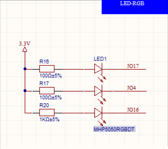
I have an ESP32-2432S024C which has an oboard RGB LEG connected to the following schematics:
How can I change this RGB color correctly? I tried to fiddle with the code and got this far:
output:
  - platform: ledc
    pin: 17
    id: gpio_17
  - platform: ledc
    pin: 4
    id: gpio_4
  - platform: ledc
    pin: 16
    id: gpio_16

light:
  - platform: monochromatic
    output: gpio_17
    name: "Light 1"
  - platform: monochromatic
    output: gpio_4
    name: "Light 2"
  - platform: monochromatic
    output: gpio_16
    name: "Light 3"
It gives me 3 controls in Home Assistant and depending how I combine them I get R,G,B … but is there a better way to have a single RGB control element?
uuuuhhhhh ya! Use the RGB Light that is for RGB lights.
Go to the esphome website and type in the search box, “RGB”
What do you mean by, “a single RGB controller” ?
I mean you have an RGB/dumb led so there are 3 color channels instead of 1 like an addressable light has. You can set up pre-configured colors or automations and then just trigger them from a “single” button/switch but, i’m not really sure what you mean.
1 Like
Awesome that worked! What threw me off a bit was the fact that i had to invert the output pins. Now it functions correctly.
To control the onboard RGB on an ESP32-2432S024C:
output:
  - platform: ledc
    inverted: true
    pin: 17
    id: onboard_rgb_1
  - platform: ledc
    inverted: true
    pin: 4
    id: onboard_rgb_2
  - platform: ledc
    inverted: true
    pin: 16
    id: onboard_rgb_3

light:
  - platform: rgb
    name: "Onboard RGB"
    red: onboard_rgb_2
    green: onboard_rgb_3
    blue: onboard_rgb_1
1 Like
Cool. You understand when to invert or what wiring configuration would call for inverted gpio, right? A lot of people dont but they know its somethig to try that might work just like someone guessing to activate a pull up/down resistor. If you had to invert the gpio then you have common anode RGB LED’s.
I would lie if I say I fully understand why. x)
My main approach is trial and error but I often times also get at least some basics down. For example I followed the complete introduction tutorial of ESPHome from smart home yourself (https://www.youtube.com/watch?v=rHxqFkNqkM0&list=PLtEjuZQyAkqGAvHjsM6G295CsKXetm-_Z&pp=iAQB).
So common anode is basically what is shown in the wireing diagram in my first post? The positive side of all of the LEDs are electrically connected at one pin, and each LED cathode has its own pin? Thats why I have to invert the logic in ESPHome?
Yes. The only reason i even brought it up is because this concept is used for a whole bunch of things like when using buttons, switches, relays, digital sensors, using transistors and a bunch of other stuff. Its a little thing that touches everything and will make your life a lot easier if you spend a little time to learn the basics.
1 Like
