Controller for 4 DC motors

I have a new project to independently open and close 4 vents in my greenhouse using 4 12 VDC motors. Due to the number of GPIOs required, it will use 2 ESP32s and will be integrated into my 2 HA instances. I don’t know ESPHome (yet) and don’t know much about electronics, so I would greatly appreciate all comments and suggestions. I will post more details, schematics and ‘code’ when they are available.

I am using 2 ESP32-DEVKITC-V4 controllers. Each exposes 24 GPIOs.

I am using 2 Toshiba TB67H400ANG controllers. Each can control 2 motors. Here is a link to the datasheet: datasheet Each controller requires 9 or maybe 11 GPIOs. The 9 controller logic pins have 100K resistors so only use 33 microamps each. Logic pin settings (H vs L) control the output voltage polarity (motor rotation direction). The 2 pins that I am not sure about are output current sense pins, used for monitoring, feedback control and overcurrent protection. They would be connected to GPIOs that have analog to digital converters, but I am not sure that I need them. Comments?

After I received the motor controllers I learned that they are SDIP, not DIP so they don’t fit breadboards or perfboards. I found adapters here: SDIP to DIP adapter I received them quickly.

I am using 8 limit switches (open and close x 4 vents). limit switch I tested some and found them around 1 msec bounce time now. Assume 10-20 msec lifetime.

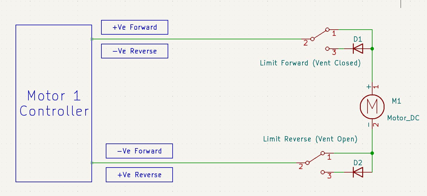
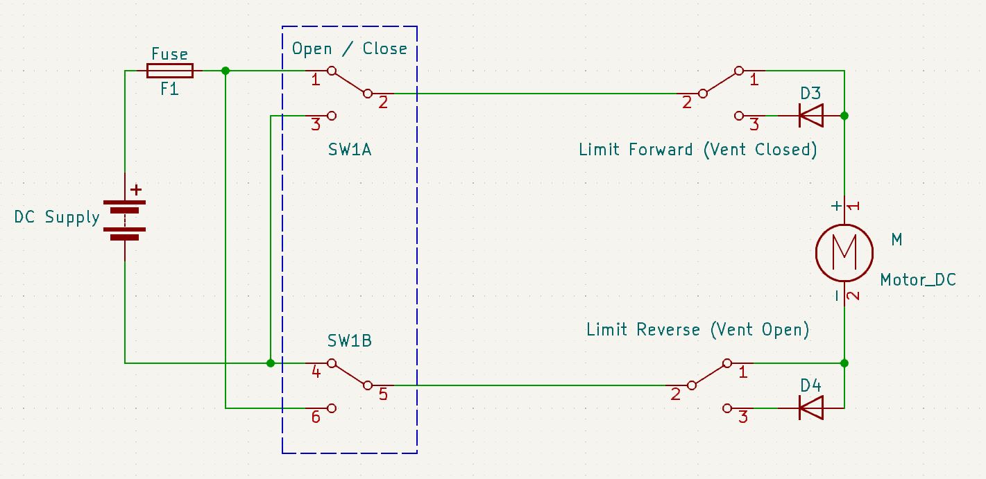
A big question was how to wire the GPIOs to the limit switches. Ideally 2 GPIOs per limit switch (1 output, 1 input), but that exceeds the number of available GPIOs. The other extreme is 2 GPIOs per 2 limit switches (1 output connected to both COM terminals, 1 input connected to both NO terminals). This has a problem that when the output GPIO is enabled, a limit switch is already tripped from the current position so the input GPIO is immediately triggered, shutting down the operation. Delaying enabling the GPIOs for 500 msec addresses this problem by giving the motor time to move the vent and free the tripped limit switch, but this adds complexity to the software. I decided to use 2 output GPIOs and 1 input GPIO per 2 limit switches. The output GPIOs will be connected to the COM terminals of the open and close limit switches (1-1) but both limit switch NO terminals will be connected to the same input GPIO. Software will have to ‘know’ the transit mode (open vs close) in order to interpret the input GPIO meaning. The action is always the same (turn the motor off) but it also has to signal HA that the appropriate operation has completed.

I plan to debounce the limit switches in hardware following this article:hardware debounce It is standard but has a good explanation of the details. I won’t be using the Schmitt trigger.

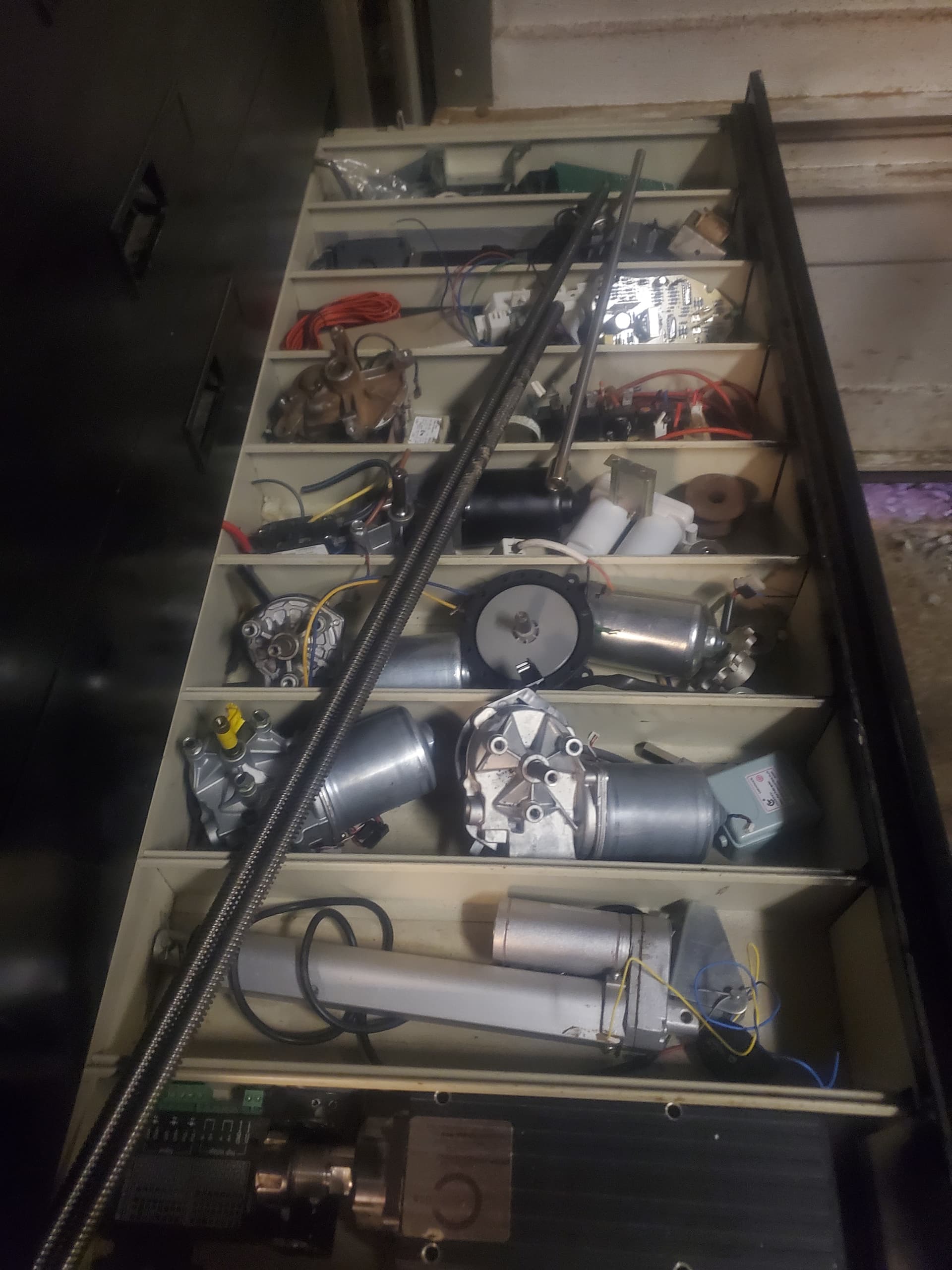
Here is a link to the motors: vent motors The output shaft rotates at 4 RPM under load, which is 15 seconds per revolution. I need a bit under 1/2 revolution so I guess 5-6 seconds transit time. The motor has 35 kg.cm (350 oz-in) of torque, which should be plenty. I think that I read somewhere (can’t find it now) that the stall current is 1.6 A. It is self locking so when it is stopped (open or closed) it should stay in place.

When a motor starts or stops a transit the microcontroller must send an event to HA which will keep a current transit count. When the count changes from 0 to 1 it will turn the 12 VDC power supply on and when it changes from 1 to 0 it will turn the power supply off. It is a 120 W (10 A) power supply that will probably generate a lot of heat. The SSR that switches the power supply input power has a logic level input pin so it can be controlled by a GPIO (not sure about current requirements, may need a resistor). I might need a small fan and ports in the box to keep the ESP32s cool.

When I started working with ESPHome I watched it build my first project. ESPHome compiled a lot of C++ code using PlatformIO. If I run into a limitation of ESPHome, I think that I should be able to define a project in VSCode and manually build the project. I worked in C++ for more than 30 years and VSCode for 2.

Quite uncommon approach for someone who claims “don’t know much about electronics”. Usually people here use ready built driver modules and so on.

Anyway, if you like soldering and datasheets, that’s good way to learn.

Your description for limits is bit odd to me, usually limit switch is just connecting GND to GPIO with pullup. What kind of switches you have if they need I/O?

I think that’s the nominal current, and stall current is somewhere in 6A range.
Your driver can probably handle that, but if you have 4 of them, 10A PSU is not sufficient to start them simultaneously.

Esphome is not some HA remote control, you don’t drive the motors in HA, but in esphome. Esphome is taking care of counting and switching.

I don’t have recent ‘hands on’ electronics experience. However, I do have 2 friends each with decades of professional electronics experience. They are guiding me and explaining the research that I am doing. For example, one recently mentioned using a bypass cap between the ESP32 5v pin and ground to filter high frequence noise, for example: bypass caps. Debouncing the limit switches just seems logical to me to reduce false readings. That is the only enhancement I plan for the limit switches, though the connections may be a bit ‘unorthodox’ :grinning:. I have also learned about MOVs. We don’t have many close lightning strikes where I live but they do happen. Also power surges can affect these circuits. I am now planning to put MOVs MOV datasheet on all of my GH electronics. I can’t easily manually control my GH if the Shelly switches or the ESP32s get fried, so this is critical to me. MOV explanation

I also want to document these concepts for others who are considering or attempting some of these things. I hope it helps someone, even if only stimulating research.

You could reduce the complexity and make the system more robust by not feeding the limit switches back to the ESP32.
Instead, use diodes with the limit switches and a timer in the ESP.

Then, there is also a manual possibility if the electronics do get damaged by just substituting a switch…

If you don’t need to run more than one motor at a time, study the controller closely, you will realise the number of GPIOs required can be really reduced. You’ll only need one ESP.

@johnBoy Would you please provide some explanation for this design? If you assume that the vent starts closed, then the open LS position would mean that pin 1 is the NC position. However, in your diagram, the close LS has the same pin triggered. If the vent is closed, then the close LS should have the open pin (NO, pin 3) triggered, because the vent contacted that LS and triggered it, stopping the close transit. The diode D2 would block the current flow and the motor wouldn’t turn. What have I missed?

Aghhh.
Sorry. I messed up while putting the drawing into KiCad…
Diode D2 is wrong. It should be the same direction as D1.

The diagram is drawn when the motor is running and the vent hasn’t reached either limit.

So if the top leg is +ve. the motor runs until the Closed limit is reached, then the power is blocked by D1.

If the power is then reversed, ( bottom leg +ve), the motor will run the other way until the open limit is reached and D2 blocks the power.

In each case, as the motor changes direction, the limit switch it was on, resets and takes the relevant diode out of circuit.


Manual…

@johnBoy Thank you for the update. Now I understand. While it does reduce the needed number of GPIOs and the complexity in both the hardware and software, it is an ‘open’ feedback loop. The ESP32 doesn’t directly ‘know’ that the vent transition completed. Certainly the diodes could be included with a ‘closed’ feedback loop for quicker response to the limit switch trigger. With a closed feedback loop I anticipated using a timer and, if the vent transition hadn’t completed when the timer expired, kill the power to the motor and raise an alarm. I don’t think that is possible with this design. I have to weight the vast complexity reduction against the closed feedback loop advantages. I really appreciate your suggestion. Also, your comment about KiCad motivated me to start checking into EDA software, something I hadn’t started yet! :slight_smile:

Yes. It’s an ‘open loop’ implementation, but could still be monitored and compared against a standard profile for opening and closing. For instance:-

The motor current could be monitored between a max and min value, for a specified time period.
If it falls out of an established envelope, stop and raise an alarm.
That would add one analogue input, assuming one motor operated at a time…

Might be worthwhile adding that, even if you go the route of all limits back to the ESP. Checking the motors are healthy and consistent.

Possibly double up on the switches to have ‘hard’ and ‘soft’ limits. Soft limits into ESP switch the motor to slow speed, before the hard limit is reached. Reduces overshoot. Or slow speed with a timer, to stop the motor before it gets to the hard limit?

So many options available…

Is it Horizon EDA you referred to?
I’ve only ever used KiCad v7 and then later, spent a little time with v8. I can recommend it, but only from the point of view that I’ve never used anything else! It’s moved on again since.

Good luck with whatever path you choose to take.
:+1:

Another thought,
Being as ESP32s are so cheap, maybe use one for each vent.
Design it for one vent. When it’s finalised, modulise it on a PCB and copy it for the other three. Their individual setup - timer changing etc, - could be done over a Bluetooth or a Wifi connection.
Depending on overall distance & location, an HMI type screen could show the current status of all of them.

Interesting idea. I have already purchased motor drivers capable of driving 2 motors each. I researched a lot of drivers to select this model (and missed that it uses SDIP rather than DIP!!!). It will all be driven by GH temp through HA, which will make the open/close decisions. I have a mesh network with a satellite in my GH so everything is already controlled by HA over WiFi. The open/close decisions will be based on temp. The only challenge is when all of the vents are open and the decision is made to turn on an exhaust fan due to continued temp rise. Then all of the vents have to be closed and re-opened when the temp drops enough. I use a 2F delta to reduce oscillation.

I haven’t really homed in on any particular EDA, just started looking. I don’t do much electronic design (through that seems to be changing) so I can’t justify spending a lot of money. However, the saying ‘you don’t get what you don’t pay for’ rings true. Especially since I haven’t done any board layout, I will need all of the help a program can provide.

I am considering using some service to produce the PCBs that I will use after the breadboard works. That would simplify working with the SDIP ICs.

@johnBoy I really appreciate all of the time and suggestions you have made.

@johnBoy I have started making ‘stuff’. I also installed KiCad v9. I found that it seems to only use chips, but I have an ESP32 dev board. Is it possible to get a model of my board (ESP32-DEVKITC-V4) to use in my design? It is essential for the PCB.

Also I have thought about your design reducing the number of GPIOs. The Toshiba motor driver that I am using has an output pin that generates a voltage that indicates the (voltage? current?) being supplied to the motor. When the vent trips a limit switch, switching the connected switch leg and stopping the power to the motor with the diode, IF that chip signal drops to zero, then this is a closed feedback loop. That is one of the first things that I will investigate. Seems promising!

Look at the Espressif website for datasheets for layouts for your ESP device.

Your motor driver chips usually have supplemental application notes to give additional support for designers that are searching their datasheets. Often the reference design provided is sufficient for your needs.

Why design your own customised motor drivers and PCBs when they are so common as pre-built modules you can drop in, available cheaply on eastern Asian shopping sites, tried, tested, and well documented? Did I say cheap?

You seem to have gotten bogged down in too much detail, using things like SSRs to switch your motors when a simple relay activated for the appropriate time may be entirely adequate and far more robust, especially if you pair it with limit switches instead of current monitors to trigger the off state. Look at your logic, especially use of GPIO ports, using one for steering, and the other for control, so you can multiplex your pin count. Do some things in hardware and others in software, appropriately.

As IOT7712 said above.

Check the manufacturers web sites for Symbols and Footprints. I believe they are in a standard file format that can be imported or installed or whatever, into KiCad.

In at least one project I did, I used a generic ‘DevKit V4’ ESP which didn’t seem to correlate exactly, to any online layout info I could find. So I ended up creating my own Symbol and Footprint to suit the device I had, using the editors built into KiCAd. It doesn’t take too long and is just another part of the ‘learning curve’ exercise. Effectively, I created a library sub-folder to keep random relays/switches/diodes/ESP symbols, that I modified to suit exactly how I wanted them to be. Some including footprints, some without.
There’s a wealth of help for KiCad in their online forum.

Monitoring motor current is ideal for feedback information. That is something I would do…
I am aware that you have the motor controller iC’s, but as said above, try not to get too bogged down with sections that are already available as cheap modules, which are tried and tested. You’ll have more time for other parts.
(Unless you really want that experience).

Google: Rube Goldberg.

As much as I want to encourage DIY projects, your plans are over the top in complexity.

Just use a motor controller module. Each module controls two motors and only need four GPIOs.

If the stall current does not exceed the rating of the controller, then you can ignore limit switches. Just use timing. I used one of these controllers to operate a linear servo to open a chest. If it took 5 seconds to open or close the chest, just drive it for 6 seconds.

Its really helpful and often times its actually necessary to include the specific details and/or pictures and definitely provide links to it online so that we can all make sure that we’re on the same page and no one’s thinking of something different.

If these are just regular vents that have a fixed open/closed position then IDK why you’d be using regular DC motors or even want to use them for this.

Why in the world would you do that??? Thats nonsensical, please dont do that! You only need 1 esp32 board if you switch to the right hardware/motors.

No clue why you chose that but, its the wrong hardware.

If you had started with the correct hardware then you wouldn’t need these either because they’re already built-in most other types. I would suggest using either something like linear actuators or better yet some stepper motors would work far better and would allow you to skip using external limit switches or any other open/closed sensors because a stepper motor counts and drives motors 1 step at a time which allows you to both track and control speed, position, acceleration, etc, etc.

No, ideally and 100% definitely not 2 gpios. You need 1 gpio and either a Gnd or a 3.3v with it.

Where are you coming up with these answers? Are you just making them up and pulling them out of thin air or what?

Before you even begin to plan out and purchase components for some advanced level project, you need to first be absolutely positive that you understand the bare minimum basics and the fundamentals of electronics/electricity and then start with 1 hardware component/sensor at a time and first learn how to fully use it so that you understand it and then move on to the next sensor/component.

Post a link or at least a picture of these vents that need rotated.

@JimmyHotcakes0235 Thank you for your suggestions. I didn’t include low level specifics because this was at the conceptual level. I listed my thoughts and wanted feedback to adjust the design. These are regular vents, 5.5’ w x 2’ h, 6" thick with insulation. They are about 40-50 lbs each for now but I will make new ones this summer that are lighter.

johnBoy mentioned a design that didn’t require GPIOs for the limit switches. I have decided to use his suggestion.

Why is the Toshiba TB67H400ANG controller wrong? Others have suggested controllers based on the ancient L298 that generates a lot of heat. This is a greenhouse and everything has to be sealed (65-70% RH) so heat is important. Those controllers still need the same open/close limit functions. The control modules I found in google searches would only replace the Toshiba IC and still required several connections from the microcontroller but didn’t provide as much control or feedback as the Toshiba part. The ‘cheap’ controllers that I found couldn’t handle the power that I expect to need. Yes, the Toshiba part has more flexibility than I need but it seems like a solid part.

How can I control vent actions (open and close) without limit switches? Yes, they open and close to specific, repeatable positions. Running time isn’t good enough due to the likelihood of drift. Stepping motors are also not acceptable due to the same drift issue. The close is especially important since it routinely reaches 0F here in the winter and I do need to open the vents on sunny winter days and close them in the evening.

I would suggest that if you are worried that heat rise from a semiconductor during their short power on phase would affect the temperature of your greenhouse, then you should abandon the entire project as it will effect global climate change. Ever heard of the butterfly effect?

I admire the use of lead free components, to save the world’s children from serious health issues as well.

Seriously, you are vastly overthinking this and making it overly complicated.

Considered a repurposed windscreen wiper motor as your actuator? Lots of torque and reproducible travel limits, and readily available at your local auto parts recycler at a cheap price point with many years of worry free operation assured. Research how the automobile manufacturers switch them so they consistently return the wiper blades to their level resting position when you turn them off at any stage of activation.

There’s nothing “regular” about vents that large! My Mom still makes me cut my food with a butter knife so, i dont know anything about big vents like that! ; )

There’s also nothing “low level” about the specifications for for the primary “thing” that your post is referring to because i was assuming some house vents or something tiny like that and not some 50lb monsters and these are important details.

Using current/power sensors are a good idea from johnBoy, i agree too. If you also read through the Esphome documentation, which you always should be doing…Ahem!!! They specifically recommend a good device and is also supported by Esphome.

Current Cover

Shelly devices are very good options too, FYI.
Shelly 2.5

Well, probably because no one knew what it was that you were trying to move and how large it was so, whenever people aren’t given the details then they’re only option is to just make best guesses based on the limited details given in OP.

How much power do you expect to need??? This is more of that “useful details” that i keep mentioning repeatedly.

Hey, where abouts do you live at? Are you within the USA? If so and your interested, i have a bunch of these geared down, very high torque, low RPM(10-12) but, most lf them actually specify using i think 29VDC if you want max torque/power.

My neighbor has a overhead garage door business and he brings me all his older overhead door systems once he replaces it with a new one…

These things aren’t cheap to purchase and it makes it that much more difficult to discard any more lf them and so they just accumulate… I have like 15 motors probably and need to find new owners for several. Most of them also come default with an optical encoder built-in and can be easily used by yourself too.

They’re free if you want some but, you’d have to cover any shipping costs.

@JimmyHotcakes0235 Yes, I live in the US and would be interested. I have an old one myself. Just seems to potentially useful to discard. How should I send you my address?