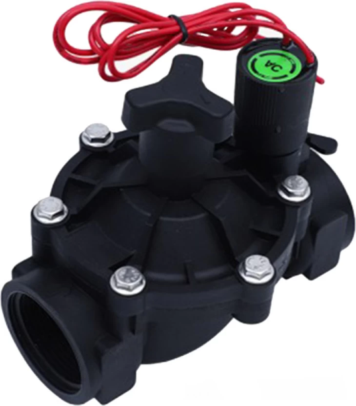
For reasons lost in the mists of time, many solenoid valves used for garden irrigation are designed to be driven by 24V AC. Made by established manufacturers like Rainbird, Hunter, and others, 24V AC has become a de facto standard. Yes, apparently there are DC versions, and even latching solenoids aimed at 9V DC (battery) operation (at a significant premium), but I have never seen one in the flesh: my local hardware and garden stores only stock the standard 24V AC models. Although one can drive these valves using DC, the voltage has to be reduced significantly, lest the poor solenoids overheat. The reason is inductance, which limits the AC current, but does not affect the steady-state DC current. Furthermore, the inductance increases significantly when the solenoid is activated, and the iron core is retracted into the coil. It is actually quite elegant, the way it is designed to self-regulate the current.


Most searches on this topic end up here:
where the effect is clearly characterised and demonstrated. Running the valves on DC, even at 12V, may be deleterious, as the power dissipated (and hence the temperature) in the solenoid coil can be significantly higher than the AC design value. And there is an additional complication: although most solenoid valves seem to work with a nominal holding current of 200-250mA, this may not be sufficient to activate the solenoid. A higher inrush current is needed.
Measuring a Rainbird solenoid and one made by a company calling themselves RainPoint, I found coil resistances of 42Ω and 30Ω respectively. At 200 mA these would dissipate 1.68W and 1.2W respectively. However, if driven by 12V DC the currents would be 285mA and 400mA, and the power dissipated would be 3.43W and 4.8W, i.e. twice and four times higher, respectively. Probably not good, especially the latter.
One way to address the issue would be to start off at 12V, and then reduce the effective voltage after a short time, thereby allowing the required inrush current to activate the solenoid, but then backing off to a safe holding level, similar to what happens automatically in the AC case, where the inductance increases during solenoid pull-in. One can do this the hard way, using PWM: Converting A Sprinkler System To DC; but this is perhaps lacking in elegance, and does expose semiconductor switches on potentially long wires/antennas snaking through the garden. Even if radiated EMI can be tamed, this is likely to cause problems with lightning damage in thunderstorm season.
Instead, what we do is to place a resistor in series with the solenoid coil, to limit the current to our target of approximately 200mA, but then we bypass the resistor with a parallel capacitor, which, at switch-on, acts like a short-circuit. As it charges up the current through the capacitor asymptotically approaches zero, though, and we soon (depending on the size of the capacitor) end up at the steady state where the total current is merely the result of the voltage (12V) divided by the total (coil plus series resistor) resistance. When we switch off the capacitor is rapidly discharged by the resistor, and we are ready for the next switch-on within a fraction of a second.
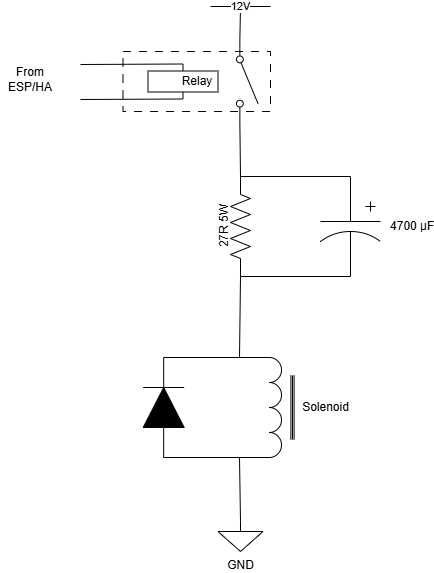
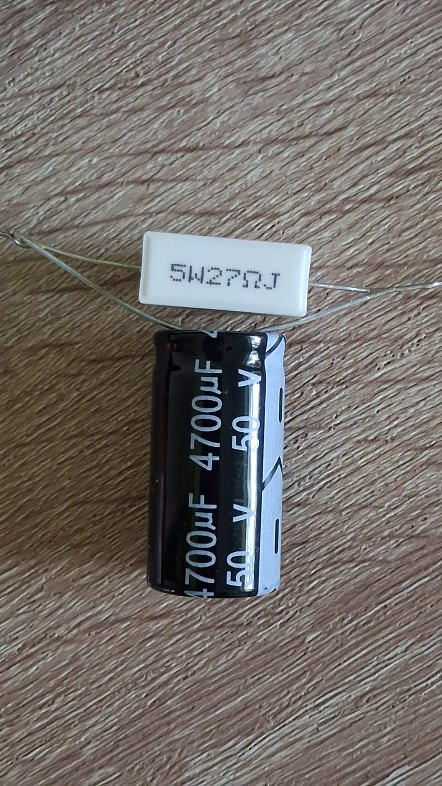
A 27Ω series resistor was used. At 12V this limits the DC current through our two test solenoids to 174mA and 210mA respectively; close enough to warrant testing. A 4700μF capacitor in parallel should supply ample current at switch-on. And indeed this works like a charm. Without the capacitor the solenoids activate down to about 10V, while with the capacitor in parallel with the resistor both solenoids reliably work at a supply voltage of as low as 8V. Even doubling the size of the capacitor does not decrease this minimum activation voltage appreciably, so we are comfortable with the values used, while running at a nominal 12V supply voltage - there is ample headroom to tolerate poor regulation and/or some voltage drop over long wires. The series resistor has to dissipate 1.2W at the 210mA holding current - but it is rated at 5W, so it shrugs it off without blinking, and the capacitor only sees a few volts, hence it should also not be strained. Optionally (but a good idea) a flyback diode across the solenoid coil helps to dissipate the voltage spike which is generated during switch-off, which can cause arcing across the relay contacts. (That spike is real - I felt it in my fingers during testing, while manually messing around with the wires.)
So now we still switch our irrigation valves using relays:
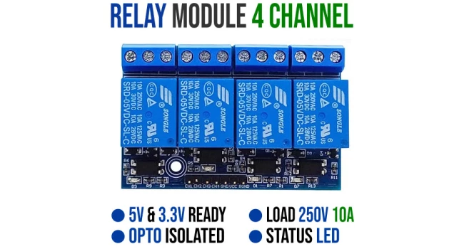
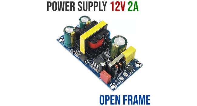
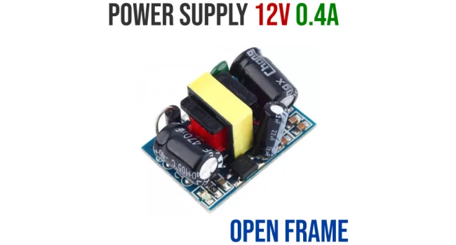
The relays are driven directly from an ESP board running Tasmota via MQTT, but the 24V AC transformer (still residing next to it in the Rainbird controller which was previously used to control our irrigation system) is not needed any more. A tiny (and cheap) 12V PSU suffices:
It is nice to have options.