Thank you Mathieu, and nice explanation as well.
How is tasmota 9.x working? Do you lose commands like people were before? I flashed https://github.com/TheEebb/tasmota-tuyamcu-fix on mine, but it’s still on 8.5.0. My first one is working well but my 2nd was giving me unknown command for TuyaMCU and DimmerRange, will work on that tomorrow.
My issue was I needed to reflow the ESP. Must have been a bad connection to Tx or Rx. Did all 3 without destroying a single pad! I ended up using the air gun to preheat the board, then the iron to get all the pads (esp ground) hot, then the air gun rotating to each one. I also used liquid flux https://www.amazon.com/dp/B00RYTD0T8 and applied with a brush liberally before I started.
Wow the LEDs, especially the main button, are bright. I wish there was a way to control it or have it only on/blink with Wi-Fi problems, but I found some self adhesive vinyl (For vinyl cutters) at the hobby store. I used the silver and put one layer over the green lights and two layers over the white light. Here’s some comparison photos:


Not to bad for $1.50. I’m pretty sure this is what the lightdims people use for 10 times the price. You can see the white light a little bit in the dark.
3 Likes
I just threw a piece of white gorilla tape on mine, but this looks much better! LOL!
So I put the vinyl on the pcb on top of the white led, but on the front plastic for the green leds because I didn’t want to rip off the rubber surrounding the green leds. This is what I used: https://www.hobbylobby.com/Scrapbook-Paper-Crafts/Die-Cut-Machines-Accessories/Vinyl-Specialty-Sheets/Silver-Self-Adhesive-Vinyl/p/80926445
The black looks like a total blackout, want to find one that lets some light through. Like the silver. Best part is the silver doesn’t look brownish like the glue from electrical tape.
You can see the glow at night but not at day, it’s pretty good
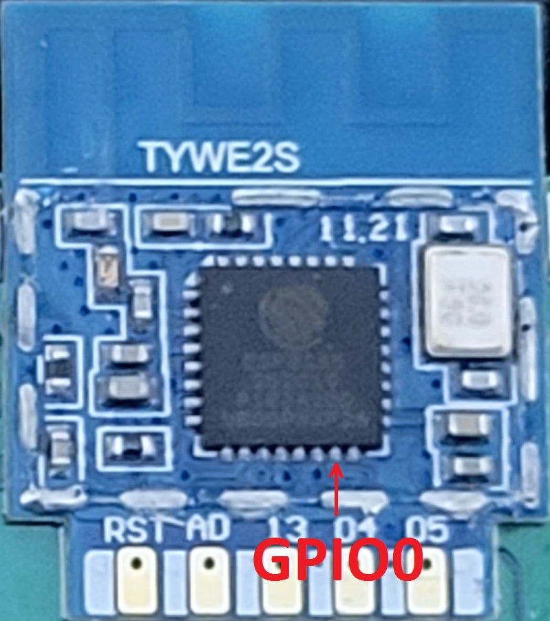
Somewhat related topic that I also posted in @flynmoose newbie guide. I’ve got another device with a TYWE2S module I’m trying to flash; however, its onboard components are going to make heat flowing the solder points very difficult to do without damaging them, at least without professional equipment. So my question which I don’t think has been asked yet is has anyone tried just removing the TYWE2S module cover/lid? Here’s a generic pic I found on the web of what I’m talking about:

It looks to be just held on with some sporadic solder around the edges. If that can be removed to expose the ESP8285 chip, then we could access the GPIO directly on the chip (pin 15 IIRC). Sure that isn’t a simple task any amateur with a soldering iron can do, but I’m confident anyone with at least some moderate experience, a steady hand, some fine wire, and a magnifying glass or scope could easily do… at least something sufficient enough to temporarily ground out GPIO0 to enter flash mode.
Again, it might be nearly as difficult as just removing whole module in the case of the Feit Dimmer; however, in other situations (e.g. my candelabra bulb I’m working on) it might be more doable. I plan to give it a whack next week if no one has tried this.
Update: the covers on these module pry off fairly easily… I gently pried mine off with a scribe. I’ll try flashing it later tonight or tomorrow, and report back how it goes.
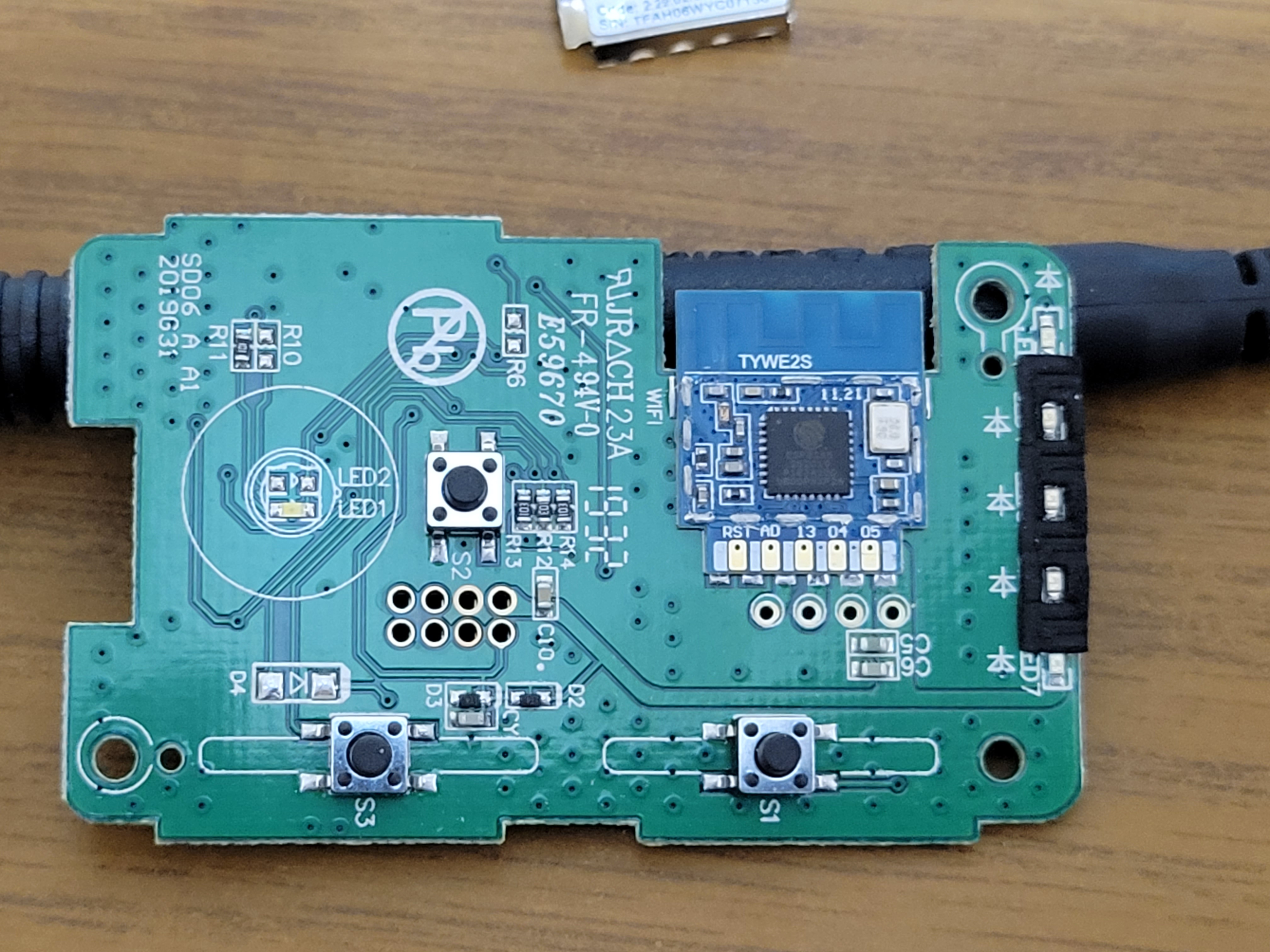
Just in case anyone was curious, here’s a pic of one my Feit dimmers with that I also removed TYWE2S module cover from. GPIO0 is the accessible (pin 15 which is the bottom 2nd from right pin on ESP chip) this way, albeit a VERY small pin to attempt to ground. I haven’t actually tried flashing this yet, but should be a fairly easy with all the other required pins already being available below the module. Just need to get a fine test lead and good magnifying glass to temporarily ground the pin.
Isn’t the 2nd problem that you also have to disable the TuyaMCU? otherwise it’ll be talking over the tx/rx lines.
I’ve had to put this on hold till probably the weekend… but I guess we’ll find out then if that’s an issue.
Even if the TuyaMCU does try talking over the TX/RX, it looks like it would be fairly simple to temporarily disconnect the traces on the rear of the board that are going to U2 pins 13 & 14 (the MCU’s TX/RX connection). Could even just cut the 3.3v going to the rest of the board and/or the MCU itself @ pin 24, but not sure how much I like that method… either way, it’s a sure sight easier/faster to do this and then reverse it than to attempt removing and reinstalling the TYWE2S module. I plan to try flashing one later this evening if I get a chance.
I really suggest stepping up your soldering game. Seriously, it’s way easier to desolder it than to hack up the board you are proposing to.
I am using this cheap 858D hot air (around 30 bucks), a bit of patience and it goes out like it should.
That’s my after:

1 Like
First my soldering game is just fine, as I’m an Avionics Technician by profession, and have nearly 30 years electronics experience overall.
Second I don’t have to do this at all, as my Feit switches were flashed via Tuya-Convert long ago. I’m doing this because I’m working on another project that involves the TYWE2S module which cannot be as easily / safely removed without the higher end equipment that I have at work. Unfortunately bringing in things like this is strictly prohibited there, and I can’t remotely justify having my own variants for an occasional project like this. I have lots of these switches just sitting in a box (replaced majority of them with MJ dimmers), so this was something I could tinker with, tear apart, mill into, etc. at home, and not really care if I damaged it while doing so.
Lastly not everyone has the skill or know-how to do what was easy for you (or myself if needed) to do. Since finding that taking off the TYWE2S module covers was super easy (again it just pries right off with little effort, and doesn’t need to be desoldered itself), I thought I’d look into and share here a potentially less daunting method of flashing these dimmers. Removing the cover and disconnecting / reconnecting those 2 long isolated traces on the back of the board is not 'hacking up the board" IMHO. I’ve seen lots of people on here and other forums severely damage their smart devices (lifted pads, damaged traces, heat stressed components, etc.) while improperly attempting to desolder / resolder their ESP module. This on the other hand utilizes the 4 pin headers on the board, so the most difficult thing is having a steady hand to touch and ground out the GPIO0 pin on the ESP if you ask me. If doing the tiny bit of disconnecting and reconnecting 2 simple traces is too difficult for someone to do, what do you suppose is going to be the result of them attempting to remove and replace the TYWE2S module???
1 Like
Wow. I didn’t mean to offend you…
The job is easy, take hot air gun, 400 C temperature, make U shaped moves - focusing on ground plane (VCC, RX TX etc pins will heat up quickly, only back - GND, looks like mechanical bond - is what will hold you up) and just maybe a minute of patience - its done, you can lift it up, and work on BIG pads to solder wires for flashing. I have only limited experience doing reflow, no near professional experience, so I can say that it is easy. If you prefer to take of the shield (which is probably as hard as taking entire thing off) and then try super fine soldering job - its up to you. I am just trying to say that you all guys might be one little step before desoldering it like a pro ($30 hot air gun).
You didn’t really, but I did feel the need to set the record straight concerning my skills and why I’m proposing this method.
As for doing it my way, I finally had a free minute to do it today, and it works / flashes just fine. I can’t express how easy it is to remove the TYWE2S cover… seriously I can remove it faster than the time it takes for your heat gun to warm up. Also the 2 traces just need 1 trace just needs to be finely cut… nothing drastic that will require jumper wire, but that is an option if someone damages them. Here’s a couple pre, during, and post cuts on my board:


Updated pics to show single cut
That’s it. Scrape scrape, cut cut, flash, and solder solder… that’s all the “super fine soldering job” one needs to do. The hardest part, if you will, was holding my grounded test lead to the ESP’s pin 15 GPIO0 for a couple seconds. Again you’re just briefly touching a ground to the above pin during power on to get the ESP chip into flashing mode. You DO NOT need to solder anything to the ESP chip / TYWE2S module! If someone doesn’t have a fine point test lead (or can’t find it like my dumb butt couldn’t), you can make a very functional ghetto one with some fine wire, a sewing needle, and some electrical tape. Here’s a pic of that ghetto setup 

I do recommend a good magnifying visor, glass, or scope though as it is a pretty fine / small pin leg on the ESP chip. But that’s it… a couple seconds on the ESP pin while the Mrs. plugged in the USB, and it was Tasmotising away! 
Updated post to reflect single Tuya MCU TX to TYWE2S RX trace cut.
4 Likes
Just an update, but for those doing the flash via my solderless method (I honestly don’t count resoldering the 2 TuyaMCU traces ), please continue being gentle / careful in removing the TYWE2S module cover.
I’ve been partially using the above method to flash some Lohas Candelabra bulbs (a bulb that utilizes multiple solder points on the back of the module in addition to the bottom copper pads… makes it an absolute bear to remove without professional solder rework stations), and I inadvertently popped off the top left smd cap. Got absolutely lucky and found it still sitting on the board… it’s not much bigger than a grain of sand, and required painstaking patience to resolder properly. I can only assume I hit it with my scribe since it’s near the hole I use to start the lid removal. It is the only 1 out of 6 bulbs I’ve flashed so far that this has happened to. The only other issue that has occurred has been tiny bits of the copper ground layer sticking to / coming off with the lid solder points from time to time. Unless it tears into the circuit area of the module this isn’t a huge issue, and I only bothered repairing one that tore without completely tearing off from the board… and that was mostly to keep it from inadvertently touching something somehow and causing a short to ground.
Anyways, just wanted to point out those issues I’ve had so you don’t get too cocky like I started to and damage things.
1 Like
Does anyone know how to sync the 3-way status in tasmota? The switch with the load doesn’t update the switch at the end of the traveler, for some reason (works vise versa).
well, I am pretty sure that 3way is done in TuyaMCU, ergo its not a wifi chip job. Ergo you shouldn’t have any problem.
Are you using two of the Feit dimmers for your 3-way, or the Feit coupled with a non-smart switch? Either way double check your wiring, as the 3-way functionality is handled via the Tuya MCU as previously mentioned.
Turns out I just needed to do a power reset to get the MCUs to talk to each other. All good now!
1 Like