Step 5 - reserved
Hello Flynmoose,
Good work with the instructions. Looking forward to reading the rest when you finish.
When I removed the TYWE2S I used higher heat 350C, might be more than I need, and made sure to preheat the whole board to prevent thermal shock. I heated the whole module to melt all the solder points at the same time and did a quick nudge and the module just slid off clean. Preheating the board and then the module after applying some clean solder and flux sucked the module back down to the board very cleanly. I like that you can replace a fried TYWE2S with a ESP8266 module with a little work.
Thanks - sorry I’ve not finished up. Work got a little crazy. And I was feeling bad I didn’t have pics. But then couldn’t quite bring myself to de-solder and re-solder a perfectly good hacked switch for fear I would bork another one…
1 Like
Flynmoose, I still have another 12 I’m converting. I would be happy to provide any pictures you may need to finish. Just let me know how I can help.
Great guide! One note: I was having issues with the TuyaMCU and DimmerRange commands in tasmota, they kept returning as unknown command. I finally was able to fix it by reflowing the solder, seems maybe a gpio had a bad connection.
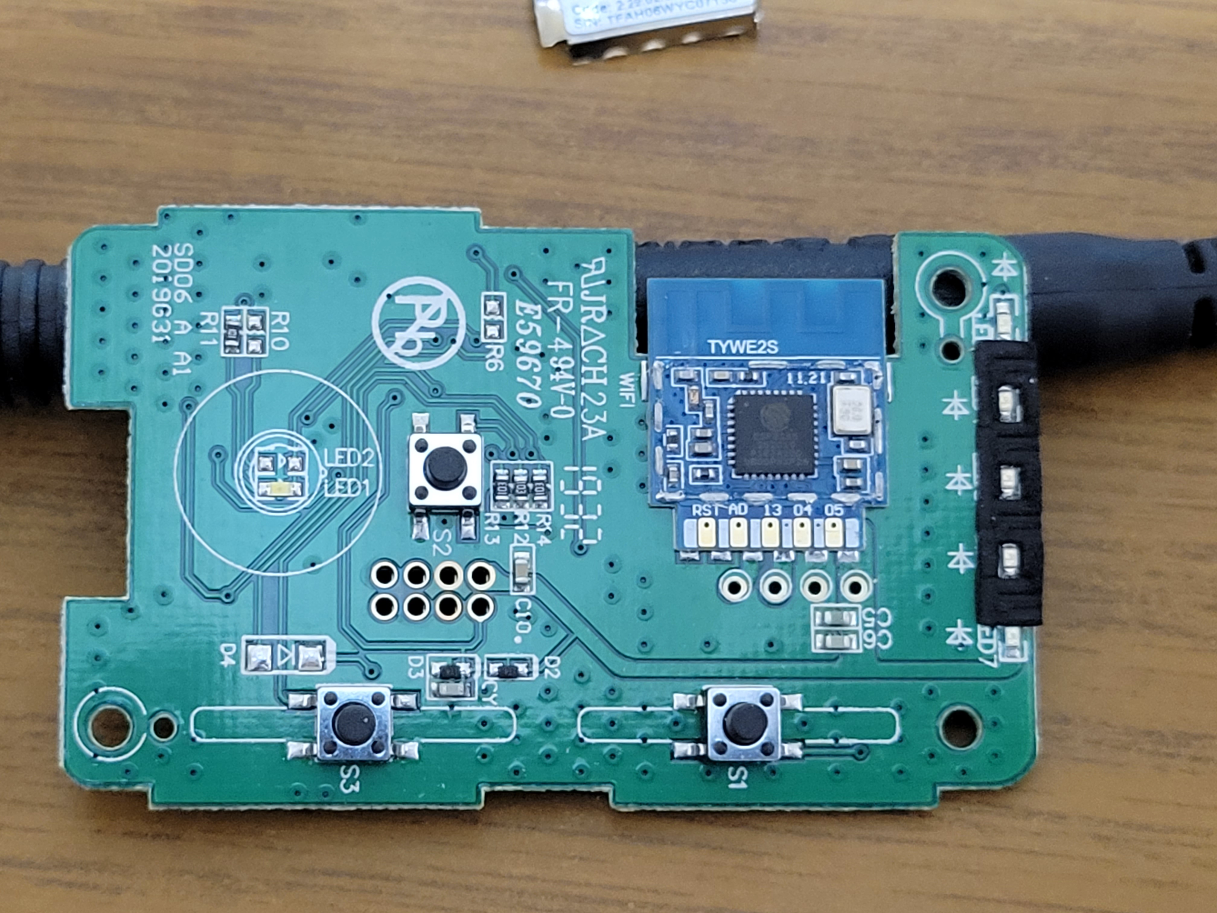
Somewhat related topic that I also posted in Costco Feit Smart Dimmer thread. I’ve got another device with a TYWE2S module I’m trying to flash; however, its onboard components are going to make heat flowing the solder points very difficult to do without damaging them, at least without professional equipment. So my question which I don’t think has been asked yet is has anyone tried just removing the TYWE2S module cover/lid? Here’s a generic pic I found on the web of what I’m talking about:

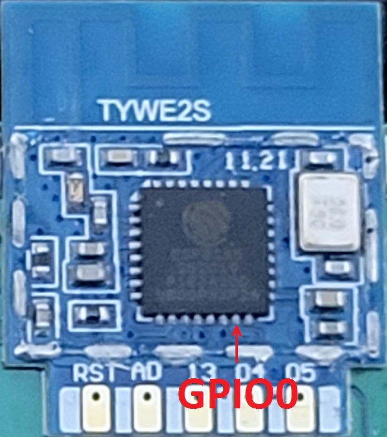
It looks to be just held on with some sporadic solder around the edges. If that can be removed to expose the ESP8285 chip, then we could access the GPIO directly on the chip (pin 15 IIRC). Sure that isn’t a simple task any amateur with a soldering iron can do, but I’m confident anyone with at least some moderate experience, a steady hand, some fine wire, and a magnifying glass or scope could easily do… at least something sufficient enough to temporarily ground out GPIO0 to enter flash mode.
Again, it might be nearly as difficult as just removing whole module in the case of the Feit Dimmer; however, in other situations (e.g. my candelabra bulb I’m working on) it might be more doable. I plan to give it a whack next week if no one has tried this.
Update: the covers on these modules pry off fairly easily… I gently pried mine off with a scribe. I’ll try flashing it later tonight or tomorrow, and report back how it goes.
1 Like
Great tutorial. It confirmed that LocalTuya was the way for me to go. I’m not totally off the cloud. (My soldering skills can barely get header pins in a Sonoff.)
1 Like
Just wanted to report back here that the (mostly) solderless method I proposed does indeed work just fine. You will need to cut 1 trace prior to flashing, and then solder it back together afterward when you’re all done (hence the “mostly” above). This is required because the TuyaMCU utilizes ESP’s TX & RX lines when powered on, and you won’t be able to properly communicate with the ESP chip to flash it if this is taking place (tested & confirmed). The 1 trace just needs to be finely cut… nothing drastic that will require jumper wire, but that is an option if someone damages them. Here’s a couple pre, during, and post cut on my board:

(removed some solder mask from the Tuya’s TX to TYWE2S RX trace)

(gently cut the trace inward away from the larger ground plane area, and verified open with DMM)

(after flashing finished I soldered the trace back together, and verified continuity with DMM)
Mind you this is the ONLY soldering you will need to do to finish converting these dimmers. Just connect your USB serial flasher to the onboard pin header, touch a grounded fine test lead to ESP8285 pin 15 (GPIO0), plug in the USB cable, and then after a few seconds remove the grounded pin. FYI I recommend using a magnifying visor, glass, or scope to make sure you’re on the right pin, and that you’re not shorting to anything else. They’re fairly inexpensive if you don’t have one (~$15 to $25 on Amazon for a decent one), and will make this MUCH easier. If you don’t have a fine test lead (or can’t find it like my dumb butt couldn’t, LOL), you can make a ghetto one with some fine wire, a sewing needle, and some electrical tape. Here’s a pic of that ghetto setup:

After this you should be able to use Tasmotizer or whatever your favorite flashing software is to flash the ESP chip. When your finished and have verified that Tasmota (or again whatever firmware you’re installing) is properly loaded, just resolder the trace you cut, and then reassemble! Easy peasy if you ask me! Also if you’re curious, no there isn’t a need to put that TYWE2S cover back on or anything… it doesn’t serve a purpose other than just protecting the components during the distribution and manufacturing process.
NOTE: At the time of this writing if you use @flynmoose pin header diagram above, be advised he inadvertently has the pin order backwards. He’s aware of it, but hasn’t had a chance to correct it yet. Until he gets said chance, the correct order is as follows:
- TX - The TRANSMIT side of the serial communications FROM the ESP TO your flash connection
- RX - The RECEIVE side of the serial (UART) communications TO the ESP FROM your flash connection
- Ground - common to the whole board (and NOT connected to AC common or Earth Ground)
- VCC - 3V3 (Positive 3.3 VDC) power to run the chip
Updated instructions / pics to single trace cut method.
2 Likes
Why not just disable the MCU by grounding the right pin?
Good question, and I did think about that. In other situations that might be the better way to go; however, three things led me away from that for this board:
- The traces for the RX & TX are fairly obvious, isolated, and long enough for anyone to work on.
- I can’t very well hold a ground lead to the MCU’s RST pin while simultaneously holding another lead to the ESP’s GPIO0, much less hold that ground in place during the entire flash process. That means soldering a jumper from a ground to a pin on the MCU, which requires a finer soldering job than just soldering 2 traces back together. As I said in previous posts I wanted this method to be easier for those that struggle with soldering. If there has to be 2 soldering jobs, might as well make them the 2 easier ones.
- I’m not entirely sure which pin on the MCU is the RST, LOL! I have the HT66F0185 datasheet, but it isn’t clear to me which pin is the reset (maybe I just missed it?). What is clear to me from both the pinout and just looking at the board, however, is which pins / traces are the RX & TX. When in doubt keep it simple and work with what you know.
1 Like
Is there an actual pin header soldered in place already on the board? It looks like from the pictures, the holes are there to attach a pin header, but not an actual header for dupont jumpers? If only holes, do you just hold your jumpers in place during flashing to make a connection? I haven’t taken mine apart yet but given this new easier method, I’m thinking about it now.
It’s just the holes, but unlike others I’ve flashed (e.g. Sonoff, etc.) where I did have to apply pressure, my pins actually fit fairly tight on this one and didn’t need it at all.
2 Likes
Just an update, but for those doing the flash via my solderless method (I honestly don’t count resoldering the 2 TuyaMCU traces  ), please continue being gentle / careful in removing the TYWE2S module cover.
I’ve been partially using the above method to flash some Lohas Candelabra bulbs (a bulb that utilizes multiple solder points on the back of the module in addition to the bottom copper pads… makes it an absolute bear to remove without professional solder rework stations), and I inadvertently popped off the top left smd cap. Got absolutely lucky and found it still sitting on the board… it’s not much bigger than a grain of sand, and required painstaking patience to resolder properly. I can only assume I hit it with my scribe since it’s near the hole I use to start the lid removal. It is the only 1 out of 6 bulbs I’ve flashed so far that this has happened to. The only other issue that has occurred has been tiny bits of the copper ground layer sticking to / coming off with the lid solder points from time to time. Unless it tears into the circuit area of the module this isn’t a huge issue, and I only bothered repairing one that tore without completely tearing off from the board… and that was mostly to keep it from inadvertently touching something somehow and causing a short to ground.
Anyways, just wanted to point out those issues I’ve had so you don’t get too cocky like I started to and damage things.
1 Like
Hi Technowizard,
Will you share a pic, if you have one, of the header connections you used? I’ve been trying to figure them out with a DMM but am uncertain.
Also, do you believe it is possible to cut just the tx line from the MCU so even if it is receiving instructions it isn’t sending anything back?
Thanks
1 Like
I listed a correction above to flynmoose’s post, but I assume this is what you’re asking for?

Actually I had thought about just cutting the TX trace after the fact myself, but have never gone back to try it. Communication wise it makes sense, and it wouldn’t hurt to try. All of my Feit dimmers were originally flashed via Tuya-Convert, and I really only came up with this method of flashing these after figuring out how to serially flash the Lohas Candelabra bulbs… with those the TYWE2S module is EXTREMELY difficult to remove without higher end equipment and/or damaging components.
2 Likes
I just tried that and it didn’t work. However, I cut the RX trace only on another board and that worked.
Here is what it looks like. You’ll see I nicked the ground plane when cutting the trace, so I’ll have to be careful when soldering so as not to create a short to ground.

2 Likes
Actually in reference to what @plstearns asked, that is the TX trace from the Tuya MCU. Remember TX goes to RX and RX to TX between chips / devices. Either way I guess that answers that question, so thanks for the info! I’ll update my instructions.
1 Like
Thanks for the clarification. I’m in the part of my life cycle where I don’t have a lot of time to tinker so the info saves me hours of troubleshooting and frustration. 
I’m using Local Tuya also for both Feit dimmers and light bulbs! A very simple process that does not involve messing with internal parts or any soldering. I was able to get about 15 light bulbs and dimmers set up with no problem. But for some reason, I have one dimmer that will not go to 100% brightness. It works on the smart life app but not with Local Tuya. How did you configure yours in local tuya? Thanks for your time!
I’ve done this to two dimmers, and I can’t seem to bridge the connection once cut. I’m using flux and a decent solder. Any tips here? I’ve had to just use a jumper wire once the connection has been severed.