[Custom integration] RF Fan — 433 MHz ceiling fans (Cecotec, Ltek and more) via ESPHome

:round_pushpin: News and support live on GitHub

I maintain this integration alone and unpaid, so everything is tracked in one place: report a bug or ask a question.

New versions no longer need announcing here: HACS offers you the update, release notes included. Otherwise, the RSS feed https://github.com/dasimon135/ha-rf-fan/releases.atom, or Watch → Releases on the repository.

This thread stays open for user-to-user help. The README is the reference and stays current — this post does not.

Hey everyone!

Following my Dooya RF433 blinds write-up, here’s the same ESP32 + CC1101 approach applied to a 433 MHz ceiling fan (mine is a Cecotec, but it’s fully generic).

This time I went a step further and built a dedicated Home Assistant custom integration“RF Fan” — so you don’t have to hand-sniff and paste codes. HA learns each remote button for you through a guided flow, and you get proper fan and light entities, plus optional timers, colour temperature (Kelvin), sound, reverse direction and natural-airflow — and an animated dashboard card that ships with it.

Result: full fan + light control from HA, no cloud, no proprietary hub, for ~$10 of hardware. Works with any RF fan whose remote uses a fixed code, not just Cecotec.

:bulb: Updated for v1.7.0 (August 2026). The wiring, the radio component and the shape of the RF codes all changed since the original write-up — thanks to @elmr91, @Relutzzzu and @Ltek, who found the problems in this thread. If you built this before, see What changed in v1.7.0 near the end.


Hardware

Component Approx. Price Source
ESP32 DevKit V1 (or clone) ~$4 AliExpress
CC1101 433 MHz module (green E07, 8 pins) ~$3 AliExpress
Dupont jumper wires (female-female) ~$2 AliExpress
433 MHz antenna (or a ~17.3 cm wire) cents
Micro-USB cable + 5 V charger already have

Total: ~$10. A small plastic enclosure is nice for the final install.

:warning: The CC1101 is a 3.3 V module — do not power it from 5 V.

The antenna goes on the CC1101, not the ESP32 — the ESP32 has no 433 MHz radio. Solder a ~17.3 cm wire (quarter-wave for 433.92 MHz) to the ANT pad, unless your module already has a spring antenna or an SMA connector.


Wiring: ESP32 + CC1101

Use two separate data pins — one for TX, one for RX.

CC1101 Pin Name ESP32 GPIO
1 GND GND
2 VCC 3V3
3 GDO0 GPIO 4 — transmit data
4 CSN GPIO 5
5 SCK GPIO 18
6 MOSI GPIO 23
7 MISO GPIO 19
8 GDO2 GPIO 13 — receive data

:warning: This is the single most common way to get stuck. Wiring both directions onto GDO0 also “works” on paper, but that one pin then has to be re-moded on every RX/TX switch, and on ESP32 that can leave remote_receiver permanently deaf — no decoded frames, not even background noise. If your gateway transmits fine but hears absolutely nothing, rule this out first. Already built with one shared pin? esphome/rf_fan_radiolib_legacy.yaml keeps that scheme working.

There are two common 8-pin CC1101 modules. Check pin 2: green E07 = VCC, blue Standard = GND. On the blue module the GPIOs are the same, only the pin positions differ — match by name, never by number.

On other boards, remap freely: only SCLK/MOSI/MISO are fixed by the chip; CS and the two GDO pins can be any free GPIO. On an ESP32-C3 SuperMini, avoid the strapping pins (GPIO2, GPIO8, GPIO9).


Step 1 — Flash the ESPHome gateway

The gateway does two jobs: it transmits the fan’s RF frames (via a transmit_rf_fan service) and listens so Home Assistant can learn your buttons (it fires an rf_fan_received event).

The radio is driven by ESPHome’s built-in cc1101 component at 433.92 MHz — no external component to install any more.

A complete, working config is in the repo: esphome/rf_fan_example.yaml.

If the sniff captures nothing at all, your remote may not be on 433.92 — try 433.42 or 434.42 via the cc1101_frequency substitution.


Step 2 — Read your protocol number and bit width

Don’t skip this one. It is the difference between codes that replay and codes that go out as nonsense.

The example ships with dump: rc_switch enabled on purpose. Open the ESPHome log, press any button on the remote, and look for:

Received RCSwitch Raw: protocol=1 data='000100110101000110100011'

Two values to copy into the substitutions at the top of the YAML:

rc_protocol: "1"     # the protocol=N value
rc_code_bits: "24"   # how many characters are inside data='...'

Why it matters: on_rc_switch hands the frame over as a 64-bit integer and throws the bit length away. Returning that integer directly gives you its decimal form (645080348), while transmit_rc_switch_raw reads its input as a bit string, one character per bit — so the frame goes out as a handful of meaningless bits. And the length cannot be recovered afterwards, because a code starting with zeros is indistinguishable from a shorter one. Hence: declare it, exactly.

Reflash after setting these two. Once guided learning works you can set dump: [] to quieten the log.

rc_switch reports one bit fewer than my remote sends

On some remotes the last bit runs straight into the inter-frame gap and the decoder drops it. Set rc_code_bits to what is decoded, and rebuild the missing trailing bit in the lambda. For a 30-bit frame whose last bit is an even parity over the other 29 (thanks @elmr91 for working this one out):

int ones = 0;
for (char c : bits) ones += (c == '1');
bits += (ones & 1) ? '1' : '0';

Step 3 — Install the RF Fan integration (HACS)

  1. HACS → three-dots → Custom repositories
  2. Add https://github.com/dasimon135/ha-rf-fan — category Integration
  3. Install RF Fan, then restart Home Assistant
  4. Settings → Devices & Services → Add IntegrationRF Fan

Requires Home Assistant 2026.5+.


Step 4 — Set up & learn your remote

In the config flow:

  1. Pick your ESPHome gateway (auto-detected).
  2. Declare what your remote can do — number of speeds, light style (none / single toggle / separate on & off), and tick any of: reverse direction, natural airflow, colour temperature, sleep timers, sound. You’re only asked for the buttons you actually have.
  3. Choose Guided learning and press each button on the physical remote when prompted — the gateway captures the frame, HA stores it. No YAML. (Manual paste is also available.)

Need to add a capability later? Use ⋮ → Reconfigure on the integration entry — it learns only the new buttons and keeps the codes you already captured, or relearns a single mis-captured one.

:warning: Any change to the gateway’s rc_code lambda, rc_protocol or rc_code_bits invalidates every code you have already learned. Matching a received frame against a learned one is exact string equality, so a code stored in the old shape will simply never match again. After touching the YAML: ⋮ → Reconfigure → Relearn RF codes.


What you get in HA

  • a fan entity with speed control (+ direction and a natural preset if enabled)
  • a light entity
  • a colour-temperature select (+ a small calibrate button)
  • a sound switch, and timer buttons (1/2/4/8 h)

State is assumed — the fan sends nothing back — but it is restored across restarts, and when you use the physical remote the integration follows along by matching the sniffed frame against the learned codes.

If that following stops working, Settings → Devices & services → RF Fan → ⋮ → Download diagnostics now has a runtime.last_unmatched_code field: the last frame that matched nothing. Compare it with the learned codes listed just above it and the mismatch is usually obvious — a decimal where you expect 1:0011…, or the wrong number of bits.


The dashboard card

The integration ships its own animated card — nothing to install, no resource to register. On a dashboard, add a card and pick RF Fan Card from the picker, or in YAML:

type: custom:rf-fan-card
entity: fan.living_room_fan

entity is the only required field. The card walks up to that fan’s device and auto-discovers the siblings (light, colour select, sound, timers), showing only the controls that exist. Blades spin at a speed-proportional rate, it follows your HA theme, and there is a visual editor. Three layouts via layout:full (default), compact, and tile (one row that lines up with HA’s native tiles).

Prefer Mushroom? The original card YAML

Needs Mushroom + vertical-stack-in-card from HACS. Adjust entity IDs to yours.

type: custom:vertical-stack-in-card
cards:
  - type: custom:mushroom-fan-card
    entity: fan.living_room_fan
    name: Living Room Fan
    icon_animation: true
    show_percentage_control: true
    show_oscillate_control: false
    collapsible_controls: false
  - type: grid
    columns: 2
    square: false
    cards:
      - type: custom:mushroom-light-card
        entity: light.living_room_fan_light
        name: Light
        icon_color: amber
        show_brightness_control: false
      - type: custom:mushroom-select-card
        entity: select.living_room_fan_color_temperature
        name: Colour
        icon: mdi:thermometer-lines
  - type: custom:mushroom-chips-card
    alignment: center
    chips:
      - type: template
        entity: fan.living_room_fan
        icon: mdi:fan
        content: Normal
        icon_color: "{{ 'blue' if state_attr('fan.living_room_fan','preset_mode') != 'natural' else 'disabled' }}"
        tap_action:
          action: perform-action
          perform_action: fan.set_preset_mode
          target: { entity_id: fan.living_room_fan }
          data: { preset_mode: normal }
      - type: template
        entity: fan.living_room_fan
        icon: mdi:weather-windy
        content: Natural
        icon_color: "{{ 'blue' if state_attr('fan.living_room_fan','preset_mode') == 'natural' else 'disabled' }}"
        tap_action:
          action: perform-action
          perform_action: fan.set_preset_mode
          target: { entity_id: fan.living_room_fan }
          data: { preset_mode: natural }
      - type: template
        entity: fan.living_room_fan
        icon: mdi:rotate-right
        content: Forward
        icon_color: "{{ 'blue' if state_attr('fan.living_room_fan','direction') != 'reverse' else 'disabled' }}"
        tap_action:
          action: perform-action
          perform_action: fan.set_direction
          target: { entity_id: fan.living_room_fan }
          data: { direction: forward }
      - type: template
        entity: fan.living_room_fan
        icon: mdi:rotate-left
        content: Reverse
        icon_color: "{{ 'blue' if state_attr('fan.living_room_fan','direction') == 'reverse' else 'disabled' }}"
        tap_action:
          action: perform-action
          perform_action: fan.set_direction
          target: { entity_id: fan.living_room_fan }
          data: { direction: reverse }
  - type: custom:mushroom-chips-card
    alignment: center
    chips:
      - type: entity
        entity: switch.living_room_fan_sound
        icon: mdi:volume-high
        content_info: name
        tap_action: { action: toggle }
      - type: entity
        entity: button.living_room_fan_timer_1h
        icon: mdi:timer-outline
        content_info: name
        tap_action:
          action: perform-action
          perform_action: button.press
          target: { entity_id: button.living_room_fan_timer_1h }
      - type: entity
        entity: button.living_room_fan_timer_2h
        icon: mdi:timer-outline
        content_info: name
        tap_action:
          action: perform-action
          perform_action: button.press
          target: { entity_id: button.living_room_fan_timer_2h }
      - type: entity
        entity: button.living_room_fan_timer_4h
        icon: mdi:timer-outline
        content_info: name
        tap_action:
          action: perform-action
          perform_action: button.press
          target: { entity_id: button.living_room_fan_timer_4h }
      - type: entity
        entity: button.living_room_fan_timer_8h
        icon: mdi:timer-outline
        content_info: name
        tap_action:
          action: perform-action
          perform_action: button.press
          target: { entity_id: button.living_room_fan_timer_8h }
      - type: entity
        entity: button.living_room_fan_recalibrate_color
        icon: mdi:target-variant
        content_info: name
        tap_action:
          action: perform-action
          perform_action: button.press
          target: { entity_id: button.living_room_fan_recalibrate_color }

Honest limitations

  • Assumed state — no RF acknowledgement from the fan; commands are one-way, HA tracks a best-effort state.
  • Fixed codes only. A remote whose frame changes on every press — a rolling code, or a counter in a few bits — cannot be learned: one action maps to exactly one code. If four presses of the same button give you four different frames, that is this case.
  • Only what rc_switch can decode. The gateway hears a frame through on_rc_switch, so a remote using a modulation rc_switch has no decoder for — Manchester/biphase, for instance — produces no event at all: the log shows raw timings and nothing else. rtl_433 -A on one press tells you what you are dealing with in one line.
  • One protocol and one bit width per gateway. rc_protocol and rc_code_bits are substitutions, not per-code properties, so a single gateway cannot serve two remotes of different geometry.
  • RX can be noisy depending on your local 433 MHz environment; TX is reliable.
  • The default rc_switch timings do not fit every fan. If a code is learned correctly but the fan ignores it, the frame is being replayed with the wrong timings, not the wrong bits — capture the original with rtl_433 -A and replace the protocol number with the measured values. There is a worked example in the repo’s Troubleshooting section.

What changed in v1.7.0

If you built this from the original write-up, three things moved:

  1. Separate RX/TX pins (GDO2 → GPIO13 for receive). The old shared-GDO0 wiring is why several people in this thread ended up with a completely deaf receiver.
  2. The gateway now emits <protocol>:<bits> instead of the raw integer — see Step 2. Reflash, then relearn every code.
  3. Toggle buttons honour repeat_count (rounded down to an odd value) instead of always going out once, so receivers that drop a lone frame now see light_toggle.

Conclusion

Same spirit as the Dooya build — ~$10 of hardware, 100% local, no cloud. The difference here is a real custom integration doing the heavy lifting (guided learning, proper entities, reconfigure, state restore, bundled card), so it should be approachable even if you have never sniffed an RF code.

Code (integration + ESPHome example): GitHub - dasimon135/ha-rf-fan: Generic Home Assistant integration for RF (433 MHz) fans — ESPHome gateway, guided code learning, optional light/timers/kelvin/sound/direction. · GitHub

Feel free to ask if you have any questions! :slightly_smiling_face: And if you try it on a different RF fan, I’d love to hear whether it works for you.


Tested with: ESPHome 2026.x / ESP-IDF 5.x / ESP32 DevKit v1 / CC1101 E07 green module / Home Assistant 2026.5+ / RF Fan 1.7.0

— Built and debugged with Claude :slight_smile:

Very nice. I solved the same problem without ESPhome. Propably interesting to check both approaches:

I have a CREATE WIND LARGE ceiling fan (the 152 cm wooden one). It’s sold in two variants: remote-only, and WiFi + remote. I have the remote-only version.

What it did:

  • Full control from HA: on/off, 6 speed presets, timers, summer/winter (rotation direction), beep on/off
  • Exposed as a native fan entity plus switch and button entities via MQTT
  • Two-way sync: the ESP32 also listens passively to the original remote, so HA stays in sync when someone uses the physical remote

One quirk of this remote: the code value drifts slightly on every press, so instead of exact matching I use nearest-neighbor matching against reference codes. There’s a small helper script to compute those from your own recordings, plus a sniffer/replay sketch to capture your remote’s codes (yours will differ from mine).

Documentation is bilingual (EN/DE) and includes wiring, protocol notes, and a troubleshooting guide covering the dead ends I hit along the way (the CC1101 async-serial-mode GDO0 config was the big one).

Repo: GitHub - jot-koehler/esp32-cc1101-fan-control: Home Assistant control for a WiFi-less 433 MHz fan via ESP32 + CC1101 — with MQTT and passive remote sync. · GitHub

— Built and debugged also with Claude :slight_smile:

guys, great info and integration! I may be tackling this soon, never done anything with ESP32 before.

while searching for hardware I ran across this; which has a lot of depth of info on the hardware options… Simple ESPSomfy RTS device · rstrouse/ESPSomfy-RTS Wiki · GitHub

Some questions…

  1. can a single controller interface into more than 1 fan? I have 2 fans I want to control
  2. do these also work with this? … ESP32 C3 Mini Plus ESP32-C3 SuperMini or Freenove ESP32-S3-WROOM (has USB-C)

thx!

Thanks, glad it’s useful!

1. Multiple fans on one gateway — Yes. The ESPHome gateway is just a dumb RF transmitter/receiver exposed as a transmit_rf_fan service; it doesn’t know or care how many fans you have. Each fan gets its own HA config entry (its own set of learned codes), and the integration passes a device identifier along with the action/code when it calls the service — same on the receive side with the esphome.rf_fan_received event. So one CC1101 + one ESP32 can happily drive both of your fans, as long as their RF codes don’t collide (in practice they won’t, since each remote has its own code space). You just run the guided learning twice, once per fan, against the same gateway.

2. Other boards (ESP32-C3 SuperMini / ESP32-S3-WROOM) — Both should work fine. The CC1101 talks SPI (SCK/MOSI/MISO/CSN) plus one GPIO for GDO0 (RX+TX data), and ESPHome lets you remap those pins to whatever’s free on your board — nothing in this project is tied to the classic ESP32 DevKit pinout, that’s just the reference wiring.

  • On the C3 SuperMini, just avoid the strapping pins (GPIO2, GPIO8, GPIO9) for CSN/GDO0/SCK etc. — pick any other free GPIOs and update esphome/rf_fan_example.yaml accordingly.
  • The ESP32-S3-WROOM (Freenove) has plenty of free GPIOs and no particular constraint here; USB-C is just a bonus for flashing.

Either way, keep wiring short (<10–15 cm) to avoid SPI glitches, and remember the CC1101 is 3.3 V only.

thx for the great reply. I found a mini on Ali that has a built-in wifi antenna connection, and includes the antenna also. LMK what you think.

and this RF module includes the 3db RF antenna

Nice picks, both are the right parts. Three things to check first:

CC1101 + 3 dB antenna: make sure both the module and the antenna are 433 MHz (they come in 315/433/868/915). A 3 dB antenna cut for the wrong band will actually make 433 worse.

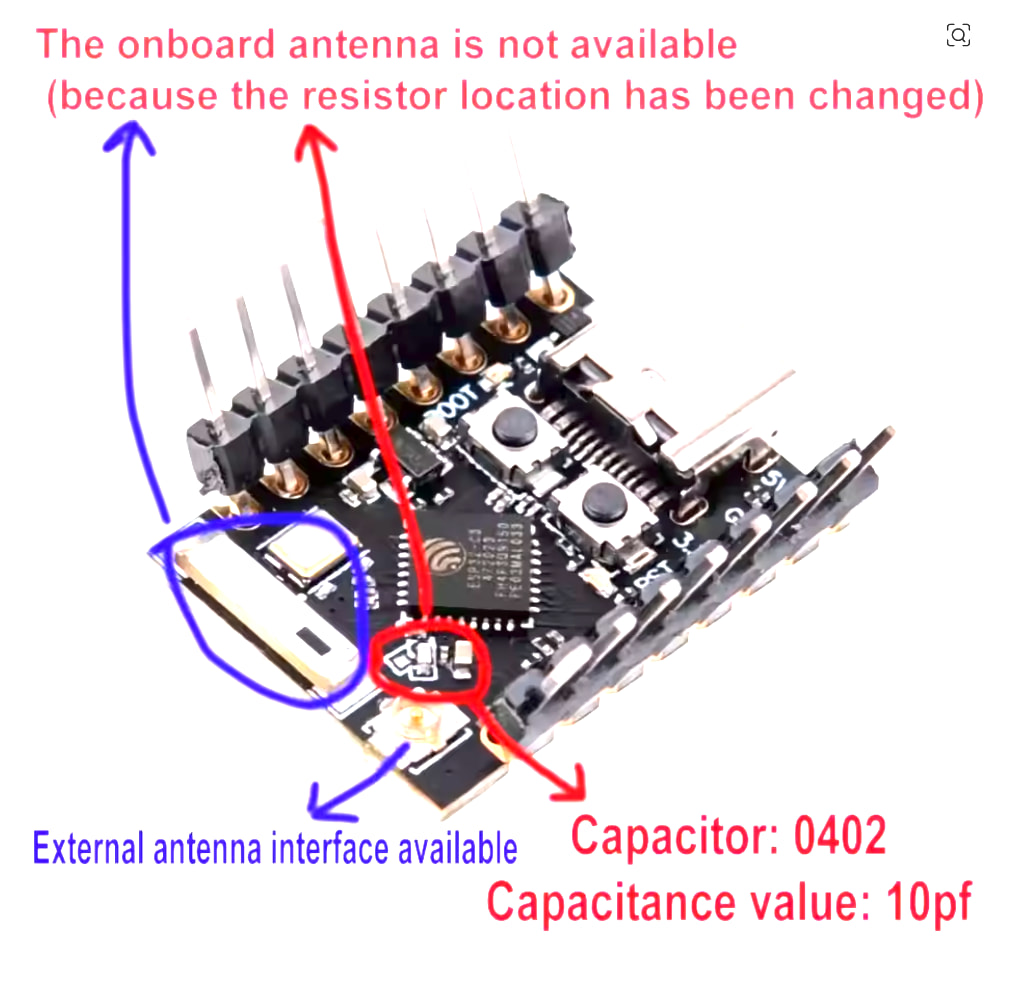
ESP32 mini w/ external wifi antenna: on most of these the u.FL connector isn’t live by default — there’s a tiny 0‑ohm resistor you have to move from the PCB antenna to the external pad, or the antenna does nothing. Also check it has enough free GPIOs: CC1101 needs SPI + 2 pins (SCK/MISO/MOSI/CS/GDO0/GDO2). Plain ESP32 or S3 is safest; the C3 SuperMini gets tight.

And don’t mix the antennas up: u.FL = 2.4 GHz (wifi), SMA = 433 MHz (fans).

Green light if the RF side is clearly 433, the ESP32 antenna is switchable, and you’ve got the pins. :+1:

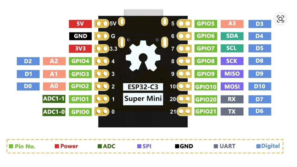
I dont see a CS on the mini’s diagram? ChatGPT says “If your board doesn’t expose GPIO5 (the traditional VSPI SS pin), simply choose another unused GPIO and configure your library to use it. Unlike SCK, MOSI, and MISO, CS can be almost any available GPIO on the ESP32. The ESP32’s GPIO matrix lets you assign the chip select signal to nearly any output pin in software”

It recommends mapping O5 or 07 to CS

Do you think this will work?

I dont know how to check if the resister needs to move. I would hope they would sell it ready to use the antenna that they include in the set :slight_smile: ?

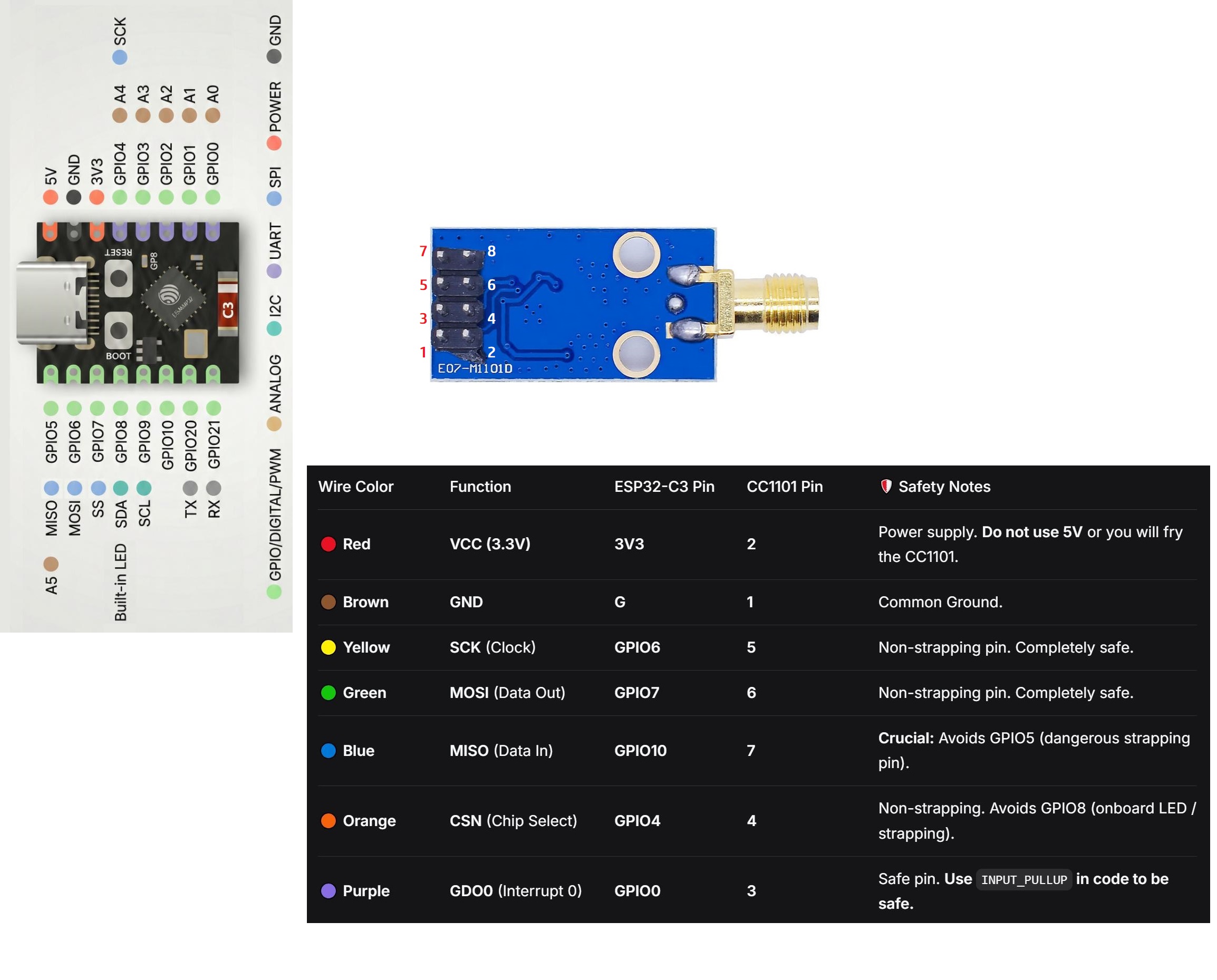
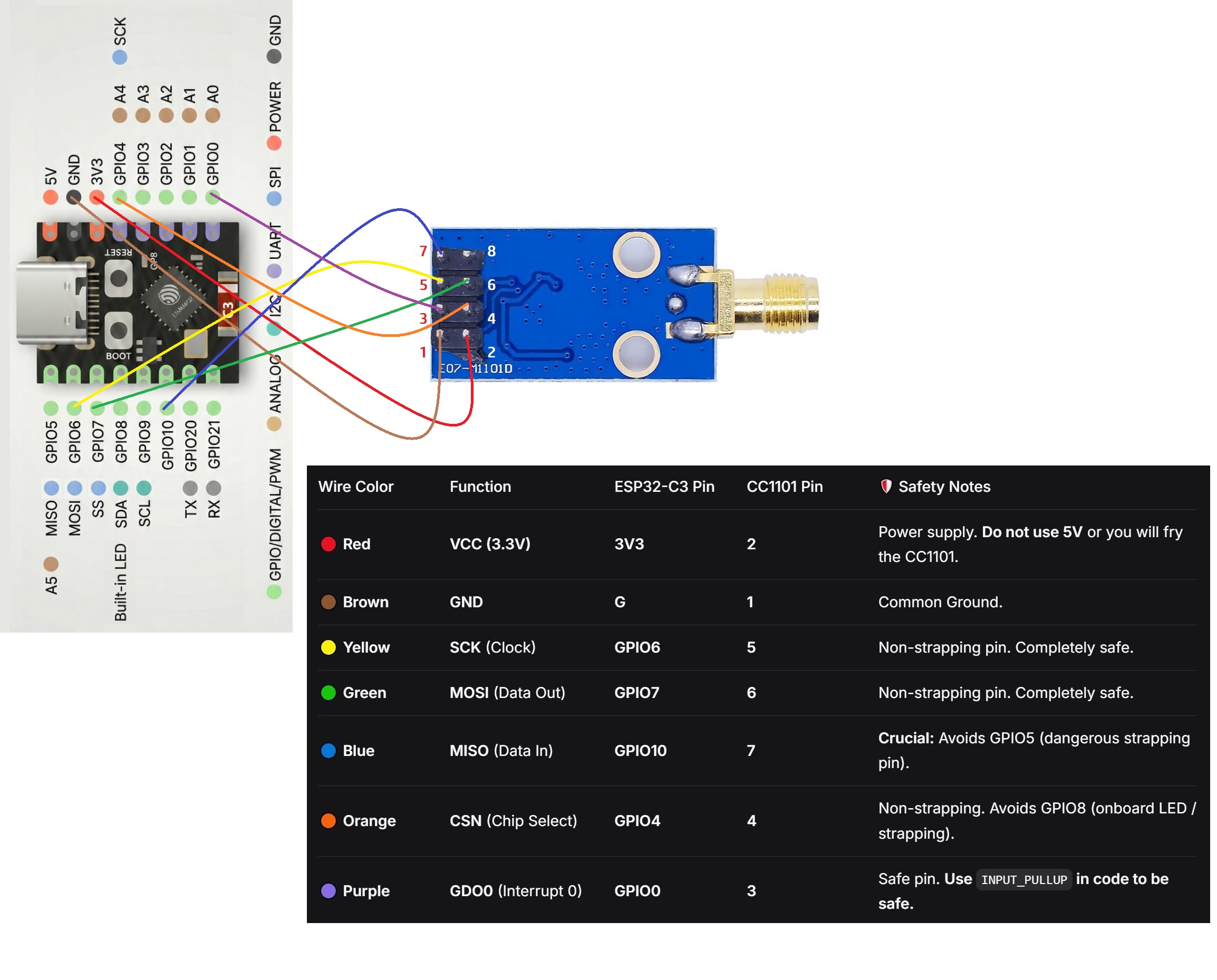
Good catch on the pinout — no pin is labeled CS because there isn’t a dedicated one. On the ESP32‑C3 (like the classic ESP32), only SCK/MISO/MOSI are fixed (GPIO8/9/10 here) — CS can be routed to any free GPIO via the chip’s GPIO matrix, so your library config just needs to point at whichever pin you pick. GPIO7 works fine.

One thing to plan for: the CC1101 also needs GDO0 and GDO2 (interrupt pins), so budget 2 more free GPIOs beyond CS — e.g. GPIO4 and GPIO3 look open on this board. Avoid GPIO20/21 if you need UART/logging.

On the antenna resistor — no way to tell from the listing photos, honestly. Worth just testing once it arrives: do a wifi scan and compare RSSI with the antenna connected vs. unplugged. If there’s no difference, the trace antenna is still active and the resistor needs moving.

I bought it, so we’ll know in a week or so :wink:

btw, some images on Ali show the resistor position. I dont want to mess with surface mount soldering, hope it has proper placement. Not sure if the external antenna is necessary for most applications but it was cheap so might as well get the external.

@eleven_gorgon45

with your comment " CC1101 is a 3.3 V module — do not power it from 5 V."
… I think the when we power the ESP32 using USB, the ESP down-converts to 3.3v for that pin to output to the CC1101, yes?

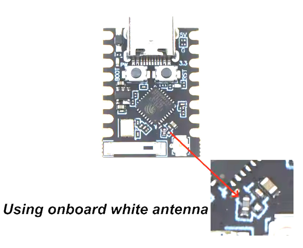
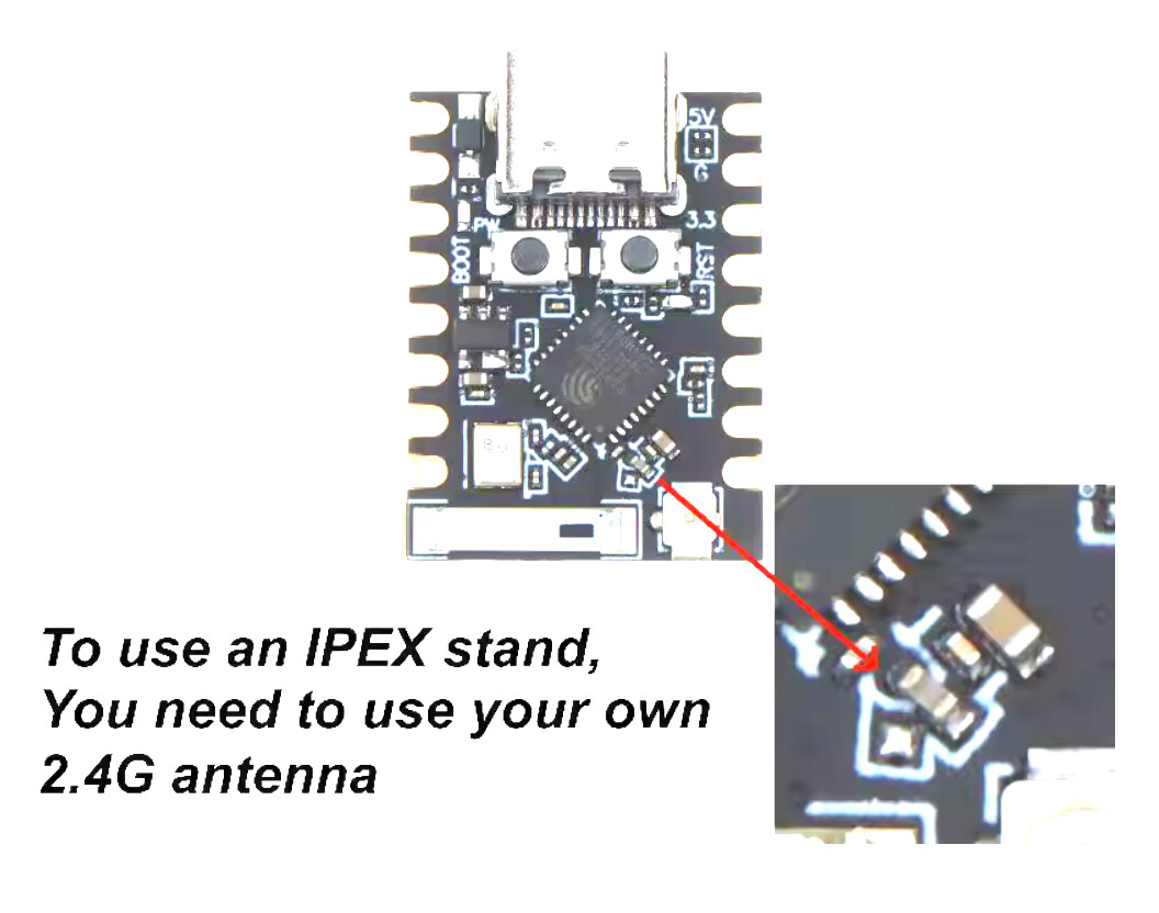
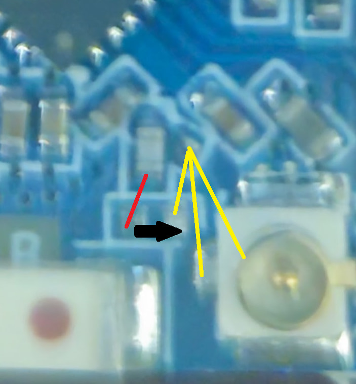
the ESP32 Mini I received is different than the photos they posted. I was not sure if the internal or external was wired up. It looked like the internal. But until I connected the external antenna, it would not connect to my wifi. So even though it looks like the cap is directionally on the white built-in antenna, seems like it is connecting to the external. strange. Leaving photos here in case anyone needs them.

Also, I toned it out… Lines of the same color show continuity between pads / connector. So I thought I was going to need a jumper where the black arrow, seems like that is not needed.

@eleven_gorgon45
Coould really use your help. I’ve spend 2 days on this. Logs (connected USB to web.esphome.io) do not show RF commands and your integrations is not ‘hearing’ them either … remote model UC7225T, FCC ID CHQ7225T

How do we troubleshoot this? thx for the help!

substitutions:
  device_name: rf-fan-gateway
  friendly_name: RF fan gateway
  cc1101_frequency: "433.92"

esphome:
  name: ${device_name}
  friendly_name: ${friendly_name}

  # Start the CC1101 in receive mode after ESPHome has initialized.
  on_boot:
    priority: -100
    then:
      - lambda: id(mycc1101).recv();

esp32:
  board: esp32-c3-devkitm-1
  variant: esp32c3
  framework:
    type: esp-idf

external_components:
  - source: github://juanboro/esphome-radiolib-cc1101@main
    components: [radiolib_cc1101]

logger:
  level: DEBUG

api:
  encryption:
    key: !secret rf_fan_api_key

  services:
    - service: transmit_rf_fan
      variables:
        action: string
        code: string
        repeat_count: int
      then:
        - remote_transmitter.transmit_rc_switch_raw:
            transmitter_id: rf_transmitter
            code: !lambda "return code;"
            protocol: 1
            repeat:
              times: !lambda "return repeat_count;"
              wait_time: 10ms

ota:
  - platform: esphome
    password: !secret ota_password

wifi:
  ssid: !secret wifi_ssid
  password: !secret wifi_password
  power_save_mode: none
  fast_connect: true

  ap:
    ssid: "${friendly_name} Fallback"
    password: !secret rf_fan_fallback_password

captive_portal:

web_server:
  port: 80

# ============================================================
# ESP32-C3 SUPER MINI <-> CC1101
#
# YOUR ACTUAL MODULE PINOUT:
#
# CC1101 pin 1  GND   -> ESP32 GND
# CC1101 pin 2  VCC   -> ESP32 3V3
# CC1101 pin 3  GDO0  -> ESP32 GPIO0
# CC1101 pin 4  CSN   -> ESP32 GPIO4
# CC1101 pin 5  SCK   -> ESP32 GPIO6
# CC1101 pin 6  MOSI  -> ESP32 GPIO7
# CC1101 pin 7  MISO  -> ESP32 GPIO10
# CC1101 pin 8  GDO2  -> DISCONNECTED
# ============================================================

spi:
  id: spi_bus
  type: single
  clk_pin: GPIO6
  mosi_pin: GPIO7
  miso_pin: GPIO10

# ============================================================
# RadioLib CC1101
#
# GDO0 is the direct OOK data path used by the component.
# GDO2 is intentionally not used.
# ============================================================

radiolib_cc1101:
  id: mycc1101

  # CC1101 pin 4 CSN -> ESP32 GPIO4
  cs_pin: GPIO4

  # CC1101 pin 3 GDO0 -> ESP32 GPIO0
  rx_pin:
    number: GPIO0
    allow_other_uses: true

  # RF frequency used by the fan remote
  frequency: ${cc1101_frequency}

  # Match ha-rf-fan project
  filter: 464kHz
  bitrate: 5

# ============================================================
# RF TRANSMITTER
#
# CC1101 GDO0 -> ESP32 GPIO0
# ============================================================

remote_transmitter:
  - id: rf_transmitter

    pin:
      number: GPIO0
      allow_other_uses: true

    carrier_duty_percent: 100%
    non_blocking: false

    on_transmit:
      then:
        - lambda: id(mycc1101).xmit();

    on_complete:
      then:
        - lambda: id(mycc1101).recv();

# ============================================================
# RF RECEIVER
#
# CC1101 GDO0 -> ESP32 GPIO0
#
# These settings match the ha-rf-fan example.
# ============================================================

remote_receiver:
  - id: rf_receiver

    pin:
      number: GPIO0
      allow_other_uses: true

    tolerance: 50%
    filter: 100us
    idle: 4ms

    dump: []

    on_rc_switch:
      then:
        - if:
            condition:
              api.connected:
            then:
              - homeassistant.event:
                  event: esphome.rf_fan_received
                  data_template:
                    device: ${device_name}
                    action: "sniff"
                    code: "{{ rc_code }}"
                  variables:
                    rc_code: !lambda "return x.code;"

Hey, sorry you’re stuck on this — 2 days of silent RF is genuinely frustrating, I feel you!

Before we go down any rabbit holes, let’s answer one simple question first: is the CC1101 hearing anything at all? Right now your remote_receiver has dump: [], which means it’ll stay silent in the logs even if it’s picking up plenty of RF noise. So step one:

remote_receiver:
  - id: rf_receiver
    ...
    dump: raw

Flash that, open the log, and mash your remote a bunch. Two possible outcomes:

  • Nothing shows up at all → this points to something physical: is there an antenna on the CC1101? (easy to forget on the bare boards, and it’s a big deal for range/sensitivity). Also worth double-checking the frequency — a lot of Cecotec-style remotes actually sit a bit off from 433.92, closer to 433.42/434.42, so it might be worth a quick sweep.
  • You see raw pulses but on_rc_switch never fires → good news, the RF path works, it’s “just” a decoding issue. There’s a known ESPHome regression where rc_switch_raw fails to decode even when raw capture works fine. Worth trying tolerance/filter tweaks, or testing on an older ESPHome release to see if it’s version-related.

Post whatever dump: raw gives you (even if it’s nothing) and we can narrow it down from there. You’re close — this is usually a “which half is broken” problem, not a “start over” problem.

@eleven_gorgon45 the for helping!

RF fan gateway logs (dump: raw)

[11:20:14][I][logger:122]: Log initialized
[11:20:14][C][safe_mode:189]: Unsuccessful boot attempts: 0
[11:20:14][D][preferences:245]: Writing 1 items: 0 cached, 1 written, 0 failed
[11:20:14][I][app:060]: Running through setup()
[11:20:14][I][radiolib_cc1101.component:016]: SPI Setup
[11:20:14][D][spi_device:395]: mode 0, data_rate 2000kHz
[11:20:14][D][radiolib_cc1101.component:024]: CC1101 setup begin init_state =0
[11:20:14]ESP-ROM:esp32c3-api1-20210207
[11:20:14]Build:Feb  7 2021
[11:20:14]rst:0x15 (USB_UART_CHIP_RESET),boot:0xf (SPI_FAST_FLASH_BOOT)
[11:20:14]Saved PC:0x420030e2
[11:20:14]SPIWP:0xee
[11:20:14]mode:DIO, clock div:1
[11:20:14]load:0x3fcd5820,len:0x1568
[11:20:14]load:0x403cbf10,len:0xc20
[11:20:14]load:0x403ce710,len:0x3084
[11:20:14]entry 0x403cbf1a
[11:20:14]I (24) boot: ESP-IDF v5.5.5 2nd stage bootloader
[11:20:14]I (24) boot: chip revision: v0.4
[11:20:14]I (24) boot: efuse block revision: v1.3
[11:20:14]I (25) boot.esp32c3: SPI Speed      : 80MHz
[11:20:14]I (25) boot.esp32c3: SPI Mode       : DIO
[11:20:14]I (25) boot.esp32c3: SPI Flash Size : 4MB
[11:20:14]I (25) boot: Enabling RNG early entropy source...
[11:20:14]I (25) boot: Partition Table:
[11:20:14]I (25) boot: ## Label            Usage          Type ST Offset   Length
[11:20:14]I (25) boot:  0 otadata          OTA data         01 00 00009000 00002000
[11:20:14]I (26) boot:  1 phy_init         RF data          01 01 0000b000 00001000
[11:20:14]I (26) boot:  2 app0             OTA app          00 10 00010000 001c0000
[11:20:14]I (26) boot:  3 app1             OTA app          00 11 001d0000 001c0000
[11:20:14]I (27) boot:  4 nvs              WiFi data        01 02 00390000 00070000
[11:20:14]I (27) boot: End of partition table
[11:20:14]I (27) esp_image: segment 0: paddr=00010020 vaddr=3c0c0020 size=27b30h (162608) map
[11:20:14]I (53) esp_image: segment 1: paddr=00037b58 vaddr=3fc90600 size=030f4h ( 12532) load
[11:20:14]I (55) esp_image: segment 2: paddr=0003ac54 vaddr=40380000 size=053c4h ( 21444) load
[11:20:14]I (60) esp_image: segment 3: paddr=00040020 vaddr=42000020 size=bc348h (770888) map
[11:20:15]I (180) esp_image: segment 4: paddr=000fc370 vaddr=403853c4 size=0b0fch ( 45308) load
[11:20:15]I (189) esp_image: segment 5: paddr=00107474 vaddr=50000000 size=00020h (    32) load
[11:20:15]I (194) boot: Loaded app from partition at offset 0x10000
[11:20:15]I (194) boot: Disabling RNG early entropy source...
[11:20:15][I][logger:122]: Log initialized
[11:20:15][C][safe_mode:189]: Unsuccessful boot attempts: 1
[11:20:15][D][preferences:245]: Writing 1 items: 0 cached, 1 written, 0 failed
[11:20:15][I][app:060]: Running through setup()
[11:20:15][I][radiolib_cc1101.component:016]: SPI Setup
[11:20:15][D][spi_device:395]: mode 0, data_rate 2000kHz
[11:20:15][D][radiolib_cc1101.component:024]: CC1101 setup begin init_state =0
[11:20:15][D][radiolib_cc1101.component:056]: CC1101 set_registers() complete - freq, bitrate, bandwidth, registers set
[11:20:15][D][radiolib_cc1101.component:029]: CC1101 setup end init_state =0
[11:20:15][C][component:209]: Setup radiolib_cc1101 took 234ms
[11:20:15][C][wifi:649]: Starting
[11:20:15][I][wifi:709]: Starting fast_connect (config) 'LWC'
[11:20:15][I][wifi:1119]: Connecting to 'LWC' (any) (priority 0, attempt 1/1 in phase INITIAL_CONNECT)...
[11:20:15][C][component:209]: Setup wifi took 56ms
[11:20:15][W][component:342]: api set Warning flag: waiting for client connection
[11:20:15][I][app:117]: setup() finished successfully!
[11:20:15][W][component:342]: wifi set Warning flag: associating to network
[11:20:15][I][app:151]: ESPHome version 2026.7.4 compiled on 2026-08-13 11:18:13 -0600
[11:20:15][I][app:158]: ESP32 Chip: ESP32-C3 rev0.4, 1 core(s)
[11:20:15][C][logger:223]: Logger:
[11:20:15][C][logger:223]:   Max Level: DEBUG
[11:20:15][C][logger:223]:   Initial Level: DEBUG
[11:20:15][C][logger:230]:   Log Baud Rate: 115200
[11:20:15][C][logger:230]:   Hardware UART: USB_SERIAL_JTAG
[11:20:15][C][logger:239]:   Task Log Buffer Size: 768 bytes
[11:20:15][C][spi:066]: SPI bus:
[11:20:15][C][spi:131]:   CLK Pin: GPIO6
[11:20:15][C][spi:131]:   SDI Pin: GPIO10
[11:20:15][C][spi:131]:   SDO Pin: GPIO7
[11:20:15][C][spi:074]:   Using HW SPI: SPI2_HOST
[11:20:15][C][radiolib_cc1101.component:038]: RadioLib-cc1101 component
[11:20:15][C][remote_receiver.esp32:120]: Remote Receiver:
[11:20:15][C][remote_receiver.esp32:120]:   Clock resolution: 1000000 hz
[11:20:15][C][remote_receiver.esp32:120]:   RMT symbols: 96
[11:20:15][C][remote_receiver.esp32:120]:   Filter symbols: 0
[11:20:15][C][remote_receiver.esp32:120]:   Receive symbols: 192
[11:20:15][C][remote_receiver.esp32:120]:   Tolerance: 50%
[11:20:15][C][remote_receiver.esp32:120]:   Carrier frequency: 0 hz
[11:20:15][C][remote_receiver.esp32:120]:   Carrier duty: 100%
[11:20:15][C][remote_receiver.esp32:120]:   Filter out pulses shorter than: 100 us
[11:20:15][C][remote_receiver.esp32:120]:   Signal is done after 4000 us of no changes
[11:20:15][C][remote_receiver.esp32:131]:   Pin: GPIO0
[11:20:15][C][remote_transmitter:060]: Remote Transmitter:
[11:20:15][C][remote_transmitter:061]:   Clock resolution: 1000000 hz
[11:20:15][C][remote_transmitter:061]:   RMT symbols: 48
[11:20:15][C][remote_transmitter:131]:   Pin: GPIO0
[11:20:15][C][captive_portal:141]: Captive Portal:
[11:20:15][C][wifi:1556]: WiFi:
[11:20:15][C][wifi:1556]:   Local MAC: 7C:4F:AD:F4:5C:AC
[11:20:15][C][wifi:1556]:   Connected: NO
[11:20:15][C][web_server:424]: Web Server:
[11:20:15][C][web_server:424]:   Address: rf-fan-gateway.local:80
[11:20:15][C][esphome.ota:098]: Over-The-Air updates:
[11:20:15][C][esphome.ota:098]:   Address: rf-fan-gateway.local:3232
[11:20:15][C][esphome.ota:098]:   Version: 2
[11:20:15][C][esphome.ota:105]:   Password configured
[11:20:15][C][safe_mode:058]: Safe Mode:
[11:20:15][C][safe_mode:058]:   Successful after: 60s
[11:20:15][C][safe_mode:058]:   Invoke after: 10 attempts
[11:20:15][C][safe_mode:058]:   Duration: 300s
[11:20:15][C][safe_mode:079]:   Bootloader rollback: support unknown
[11:20:15][C][web_server.ota:256]: Web Server OTA
[11:20:15][C][api:269]: Server:
[11:20:15][C][api:269]:   Address: rf-fan-gateway.local:6053
[11:20:15][C][api:269]:   Listen backlog: 4
[11:20:15][C][api:269]:   Max connections: 5
[11:20:15][C][api:276]:   Noise encryption: YES
[11:20:15][C][mdns:259]: mDNS:
[11:20:15][C][mdns:259]:   Hostname: rf-fan-gateway
[11:20:19][I][wifi:1600]: Connected
[11:20:19][D][wifi:1617]: Disabling AP
[11:20:19][C][wifi:1259]:   IP Address: 192.168.2.67
[11:20:19][C][wifi:1270]:   SSID: 'LWC'
[11:20:19][C][wifi:1270]:   BSSID: 82:11:22:28:A7:B9
[11:20:19][C][wifi:1270]:   Hostname: 'rf-fan-gateway'
[11:20:19][C][wifi:1270]:   Signal strength: -67 dB ▂▄▆█
[11:20:19][C][wifi:1270]:   Channel: 11
[11:20:19][C][wifi:1270]:   Subnet: 255.255.255.0
[11:20:19][C][wifi:1270]:   Gateway: 192.168.2.1
[11:20:19][C][wifi:1270]:   DNS1: 192.168.2.50
[11:20:19][C][wifi:1270]:   DNS2: 1.1.1.1
[11:20:19][D][wifi:2316]: Saved fast_connect settings
[11:20:19][W][component:365]: wifi cleared Warning flag
[11:20:23][D][api:253]: Accept 192.168.2.61
[11:20:23][W][component:365]: api cleared Warning flag
[11:20:23][D][api.connection:2526]: Home Assistant 2026.8.1 (192.168.2.61): connected
[11:21:15][I][safe_mode:142]: Boot seems successful; resetting boot loop counter
[11:21:15][D][preferences:245]: Writing 2 items: 0 cached, 2 written, 0 failed
[11:25:19][D][wifi:2480]: Roam scan (-67 dBm, attempt 1/3)

code…

substitutions:
  device_name: rf-fan-gateway
  friendly_name: RF fan gateway
  cc1101_frequency: "433.92"

esphome:
  name: ${device_name}
  friendly_name: ${friendly_name}

  # Start the CC1101 in receive mode after ESPHome has initialized.
  on_boot:
    priority: -100
    then:
      - lambda: id(mycc1101).recv();

esp32:
  board: esp32-c3-devkitm-1
  variant: esp32c3
  framework:
    type: esp-idf

external_components:
  - source: github://juanboro/esphome-radiolib-cc1101@main
    components: [radiolib_cc1101]

logger:
  level: DEBUG

api:
  encryption:
    key: !secret rf_fan_api_key

  actions:
    - action: transmit_rf_fan
      variables:
        action: string
        code: string
        repeat_count: int
      then:
        - remote_transmitter.transmit_rc_switch_raw:
            transmitter_id: rf_transmitter
            code: !lambda "return code;"
            protocol: 1
            repeat:
              times: !lambda "return repeat_count;"
              wait_time: 10ms

ota:
  - platform: esphome
    password: !secret ota_password

wifi:
  ssid: !secret wifi_ssid
  password: !secret wifi_password
  power_save_mode: none
  fast_connect: true

  ap:
    ssid: "${friendly_name} Fallback"
    password: !secret rf_fan_fallback_password

captive_portal:

web_server:
  port: 80

# ============================================================
# ESP32-C3 SUPER MINI <-> CC1101
#
# YOUR ACTUAL MODULE PINOUT:
#
# CC1101 pin 1  GND   -> ESP32 GND
# CC1101 pin 2  VCC   -> ESP32 3V3
# CC1101 pin 3  GDO0  -> ESP32 GPIO0
# CC1101 pin 4  CSN   -> ESP32 GPIO4
# CC1101 pin 5  SCK   -> ESP32 GPIO6
# CC1101 pin 6  MOSI  -> ESP32 GPIO7
# CC1101 pin 7  MISO  -> ESP32 GPIO10
# CC1101 pin 8  GDO2  -> DISCONNECTED
# ============================================================

spi:
  id: spi_bus
  type: single
  clk_pin: GPIO6
  mosi_pin: GPIO7
  miso_pin: GPIO10

# ============================================================
# RadioLib CC1101
#
# GDO0 is the direct OOK data path used by the component.
# GDO2 is intentionally not used.
# ============================================================

radiolib_cc1101:
  id: mycc1101

  # CC1101 pin 4 CSN -> ESP32 GPIO4
  cs_pin: GPIO4

  # CC1101 pin 3 GDO0 -> ESP32 GPIO0
  rx_pin:
    number: GPIO0
    allow_other_uses: true

  # RF frequency used by the fan remote
  frequency: ${cc1101_frequency}

  # Match ha-rf-fan project
  filter: 464kHz
  bitrate: 5

# ============================================================
# RF TRANSMITTER
#
# CC1101 GDO0 -> ESP32 GPIO0
# ============================================================

remote_transmitter:
  - id: rf_transmitter

    pin:
      number: GPIO0
      allow_other_uses: true

    carrier_duty_percent: 100%
    non_blocking: false

    on_transmit:
      then:
        - lambda: id(mycc1101).xmit();

    on_complete:
      then:
        - lambda: id(mycc1101).recv();

# ============================================================
# RF RECEIVER
#
# CC1101 GDO0 -> ESP32 GPIO0
#
# These settings match the ha-rf-fan example.
# ============================================================

remote_receiver:
  - id: rf_receiver

    pin:
      number: GPIO0
      allow_other_uses: true

    tolerance: 50%
    filter: 100us
    idle: 4ms

    dump: raw

    on_rc_switch:
      then:
        - if:
            condition:
              api.connected:
            then:
              - homeassistant.event:
                  event: esphome.rf_fan_received
                  data_template:
                    device: ${device_name}
                    action: "sniff"
                    code: "{{ rc_code }}"
                  variables:
                    rc_code: !lambda "return x.code;"

Thanks for posting the full log, that actually tells us a lot!

The key thing: your log shows a totally clean boot, WiFi up, API connected… and then absolute silence from the receiver. Not even a single “Received Raw” line, even 5 minutes in (I can see the WiFi roam scan at 11:25, so the device was alive and listening the whole time). That’s the important clue — it’s not a decoding problem, it’s that nothing is reaching remote_receiver at all, not even background noise.

Given that, I don’t think this is a rc_switch parsing issue — I think it’s the classic single-pin GDO0 sharing conflict. You’ve got three things fighting over GPIO0: radiolib_cc1101’s rx_pin, remote_transmitter, and remote_receiver, all with allow_other_uses: true. Every time mycc1101.recv()/.xmit() runs, it re-touches that pin’s mode — and on ESP32, remote_receiver needs the pin cleanly routed through the RMT peripheral to actually capture pulses. If something else re-asserts a plain GPIO mode on top of that, RMT capture goes silent exactly like what you’re seeing (there’s a very similar confirmed bug in the newer built-in cc1101: component, GH issue #16876 — same root cause, different component).

Two things worth trying, in order of effort:

Quick sanity check: wire GDO2 (currently disconnected) to a spare GPIO, and add a second, totally independent remote_receiver on that pin only — no allow_other_uses, nothing else touching it. If that one starts showing raw noise when you press the remote, it confirms the single-pin sharing is the culprit.

Real fix: switch to dual-pin wiring — GDO0 for TX (remote_transmitter), GDO2 for RX (remote_receiver), each on its own dedicated GPIO. This is actually the officially recommended wiring now (the readme itself points at the newer built-in cc1101: component, which documents dual-pin as the recommended scheme specifically to avoid this class of conflict). It’s a one-wire change plus a config tweak, no new hardware needed since GDO2 is already broken out on your module.

Given you’re getting zero signal rather than garbled signal, I’d bet on the pin-sharing conflict over an RF/antenna problem. Try the GDO2 test first since it’s 5 minutes of work — let me know what you get.

I’m not seeing any comms in the log.

I updated the wiring per your suggestion…

Updated YAML attached. Please LMK if it is correct, I had to use AI since I kept getting errors on saving (I’ve never worked with ESP32 before)

Reconnected
[14:28:48][I][logger:122]: Log initialized
[14:28:48][C][safe_mode:189]: Unsuccessful boot attempts: 0
[14:28:48][D][preferences:245]: Writing 1 items: 0 cached, 1 written, 0 failed
[14:28:48][I][app:060]: Running through setup()
[14:28:48][I][radiolib_cc1101.component:016]: SPI Setup
[14:28:48][D][spi_device:395]: mode 0, data_rate 2000kHz
[14:28:48][D][radiolib_cc1101.component:024]: CC1101 setup begin init_state =0
[14:28:48][D][radiolib_cc1101.component:056]: CC1101 set_registers() complete - freq, bitrate, bandwidth, registers set
[14:28:48][D][radiolib_cc1101.component:029]: CC1101 setup end init_state =0
[14:28:48][C][component:209]: Setup radiolib_cc1101 took 236ms
[14:28:48][C][wifi:649]: Starting
[14:28:48][I][wifi:709]: Starting fast_connect (config) 'LWC'
[14:28:48][I][wifi:1119]: Connecting to 'LWC' (any) (priority 0, attempt 1/1 in phase INITIAL_CONNECT)...
[14:28:48][C][component:209]: Setup wifi took 52ms
[14:28:48][W][component:342]: api set Warning flag: waiting for client connection
[14:28:48][I][app:117]: setup() finished successfully!
[14:28:48][W][component:342]: wifi set Warning flag: associating to network
[14:28:48][I][app:151]: ESPHome version 2026.7.4 compiled on 2026-08-13 14:23:06 -0600
[14:28:48][I][app:158]: ESP32 Chip: ESP32-C3 rev0.4, 1 core(s)
[14:28:48][C][logger:223]: Logger:
[14:28:48][C][logger:223]:   Max Level: DEBUG
[14:28:48][C][logger:223]:   Initial Level: DEBUG
[14:28:48][C][logger:230]:   Log Baud Rate: 115200
[14:28:48][C][logger:230]:   Hardware UART: USB_SERIAL_JTAG
[14:28:48][C][logger:239]:   Task Log Buffer Size: 768 bytes
[14:28:48][C][spi:066]: SPI bus:
[14:28:48][C][spi:131]:   CLK Pin: GPIO6
[14:28:48][C][spi:131]:   SDI Pin: GPIO10
[14:28:48][C][spi:131]:   SDO Pin: GPIO7
[14:28:48][C][spi:074]:   Using HW SPI: SPI2_HOST
[14:28:48][C][radiolib_cc1101.component:038]: RadioLib-cc1101 component
[14:28:48][C][remote_receiver.esp32:120]: Remote Receiver:
[14:28:48][C][remote_receiver.esp32:120]:   Clock resolution: 1000000 hz
[14:28:48][C][remote_receiver.esp32:120]:   RMT symbols: 96
[14:28:48][C][remote_receiver.esp32:120]:   Filter symbols: 0
[14:28:48][C][remote_receiver.esp32:120]:   Receive symbols: 192
[14:28:48][C][remote_receiver.esp32:120]:   Tolerance: 50%
[14:28:48][C][remote_receiver.esp32:120]:   Carrier frequency: 0 hz
[14:28:48][C][remote_receiver.esp32:120]:   Carrier duty: 100%
[14:28:48][C][remote_receiver.esp32:120]:   Filter out pulses shorter than: 100 us
[14:28:48][C][remote_receiver.esp32:120]:   Signal is done after 4000 us of no changes
[14:28:48][C][remote_receiver.esp32:131]:   Pin: GPIO1
[14:28:48][C][remote_transmitter:060]: Remote Transmitter:
[14:28:48][C][remote_transmitter:061]:   Clock resolution: 1000000 hz
[14:28:48][C][remote_transmitter:061]:   RMT symbols: 48
[14:28:48][C][remote_transmitter:131]:   Pin: GPIO0
[14:28:48][C][captive_portal:141]: Captive Portal:
[14:28:48][C][wifi:1556]: WiFi:
[14:28:48][C][wifi:1556]:   Local MAC: 7C:4F:AD:F4:5C:AC
[14:28:48][C][wifi:1556]:   Connected: NO
[14:28:48][C][web_server:424]: Web Server:
[14:28:48][C][web_server:424]:   Address: rf-fan-gateway.local:80
[14:28:48][C][esphome.ota:098]: Over-The-Air updates:
[14:28:48][C][esphome.ota:098]:   Address: rf-fan-gateway.local:3232
[14:28:48][C][esphome.ota:098]:   Version: 2
[14:28:48][C][esphome.ota:105]:   Password configured
[14:28:48][C][safe_mode:058]: Safe Mode:
[14:28:48][C][safe_mode:058]:   Successful after: 60s
[14:28:48][C][safe_mode:058]:   Invoke after: 10 attempts
[14:28:48][C][safe_mode:058]:   Duration: 300s
[14:28:48][C][safe_mode:079]:   Bootloader rollback: support unknown
[14:28:48][C][web_server.ota:256]: Web Server OTA
[14:28:48][C][api:269]: Server:
[14:28:48][C][api:269]:   Address: rf-fan-gateway.local:6053
[14:28:48][C][api:269]:   Listen backlog: 4
[14:28:48][C][api:269]:   Max connections: 5
[14:28:48][C][api:276]:   Noise encryption: YES
[14:28:48][C][mdns:259]: mDNS:
[14:28:48][C][mdns:259]:   Hostname: rf-fan-gateway

YAML config…


# ============================================================
# rf-fan-gateway ESPHome config
# Version: 1.1  (2026-08-13)
#   - Split CC1101 GDO0/GDO2 onto dedicated TX/RX GPIOs
#   - Fixed invalid radiolib_cc1101 tx_pin key
#   - Fixed invalid allow_other_uses on exclusive GPIO0
# Source: Claude
# ============================================================

substitutions:
  device_name: rf-fan-gateway
  friendly_name: RF fan gateway
  cc1101_frequency: "433.92"

esphome:
  name: ${device_name}
  friendly_name: ${friendly_name}

  # Start the CC1101 in receive mode after ESPHome has initialized.
  on_boot:
    priority: -100
    then:
      - lambda: id(mycc1101).recv();

esp32:
  board: esp32-c3-devkitm-1
  variant: esp32c3
  framework:
    type: esp-idf

external_components:
  - source: github://juanboro/esphome-radiolib-cc1101@main
    components: [radiolib_cc1101]

logger:
  level: DEBUG

api:
  encryption:
    key: !secret rf_fan_api_key

  actions:
    - action: transmit_rf_fan
      variables:
        action: string
        code: string
        repeat_count: int
      then:
        - remote_transmitter.transmit_rc_switch_raw:
            transmitter_id: rf_transmitter
            code: !lambda "return code;"
            protocol: 1
            repeat:
              times: !lambda "return repeat_count;"
              wait_time: 10ms

ota:
  - platform: esphome
    password: !secret ota_password

wifi:
  ssid: !secret wifi_ssid
  password: !secret wifi_password
  power_save_mode: none
  fast_connect: true

  ap:
    ssid: "${friendly_name} Fallback"
    password: !secret rf_fan_fallback_password

captive_portal:

web_server:
  port: 80

# ============================================================
# ESP32-C3 SUPER MINI <-> CC1101
#
# YOUR ACTUAL MODULE PINOUT:
#
# CC1101 pin 1  GND   -> ESP32 GND
# CC1101 pin 2  VCC   -> ESP32 3V3
# CC1101 pin 3  GDO0  -> ESP32 GPIO0  (TX only)
# CC1101 pin 4  CSN   -> ESP32 GPIO4
# CC1101 pin 5  SCK   -> ESP32 GPIO6
# CC1101 pin 6  MOSI  -> ESP32 GPIO7
# CC1101 pin 7  MISO  -> ESP32 GPIO10
# CC1101 pin 8  GDO2  -> ESP32 GPIO1  (RX only)
# ============================================================

spi:
  id: spi_bus
  type: single
  clk_pin: GPIO6
  mosi_pin: GPIO7
  miso_pin: GPIO10

# ============================================================
# RadioLib CC1101
#
# Dual-pin wiring: GDO0 carries TX data, GDO2 carries RX data.
# This is the vendor-recommended wiring for ESP32 (esp-idf) when
# both transmit and receive are needed - see project README:
# https://github.com/juanboro/esphome-radiolib-cc1101
# ============================================================

radiolib_cc1101:
  id: mycc1101

  # CC1101 pin 4 CSN -> ESP32 GPIO4
  cs_pin: GPIO4

  # CC1101 pin 8 GDO2 -> ESP32 GPIO1 (RX)
  # radiolib_cc1101 only exposes cs_pin/rx_pin - TX is driven entirely
  # by the remote_transmitter's own pin block on GDO0/GPIO0 below.
  rx_pin:
    number: GPIO1
    allow_other_uses: true

  # RF frequency used by the fan remote
  frequency: ${cc1101_frequency}

  # Match ha-rf-fan project
  filter: 464kHz
  bitrate: 5

# ============================================================
# RF TRANSMITTER
#
# CC1101 GDO0 -> ESP32 GPIO0 (dedicated TX pin)
# ============================================================

remote_transmitter:
  - id: rf_transmitter

    pin:
      number: GPIO0

    carrier_duty_percent: 100%
    non_blocking: false

    on_transmit:
      then:
        - lambda: id(mycc1101).xmit();

    on_complete:
      then:
        - lambda: id(mycc1101).recv();

# ============================================================
# RF RECEIVER
#
# CC1101 GDO2 -> ESP32 GPIO1 (dedicated RX pin)
#
# These settings match the ha-rf-fan example.
# ============================================================

remote_receiver:
  - id: rf_receiver

    pin:
      number: GPIO1
      allow_other_uses: true

    tolerance: 50%
    filter: 100us
    idle: 4ms

    dump: raw

    on_rc_switch:
      then:
        - if:
            condition:
              api.connected:
            then:
              - homeassistant.event:
                  event: esphome.rf_fan_received
                  data_template:
                    device: ${device_name}
                    action: "sniff"
                    code: "{{ rc_code }}"
                  variables:
                    rc_code: !lambda "return x.code;"

also, it has trouble authenticating often… I usually have to power-off/on multiple times for it to work? (unrelated to RF, I know)

[14:25:52][C][mdns:259]: Hostname: rf-fan-gateway
[14:25:55][W][wifi_esp32:852]: Disconnected ssid='LWC' bssid=82:11:22:28:A7:B9 reason='Auth Expired'
[14:25:55][W][wifi:1703]: Connecting to network failed (callback)
[14:25:55][D][wifi:1882]: Retry phase: INITIAL_CONNECT → SCAN_CONNECTING
[14:25:55][D][wifi:1325]: Starting scan
[14:25:58][D][wifi:1485]: Found networks:
[14:25:58][I][wifi:1456]: - 'LWC' (82:11:22:28:A7:B9) ▂▄▆█ Ch:11 -86dB P:0
[14:25:58][I][wifi:1119]: Connecting to 'LWC' (82:11:22:28:A7:B9) (priority 0, attempt 1/2 in phase SCAN_CONNECTING)...
[14:25:59][W][wifi_esp32:852]: Disconnected ssid='LWC' bssid=82:11:22:28:A7:B9 reason='Auth Expired'
[14:25:59][W][wifi:1703]: Connecting to network failed (callback)
[14:25:59][D][wifi:2064]: Failed 'LWC' (82:11:22:28:A7:B9), priority 0 → 0
[14:25:59][D][wifi:2135]: Retry attempt 2/2 in phase SCAN_CONNECTING
[14:25:59][I][wifi:1119]: Connecting to 'LWC' (82:11:22:28:A7:B9) (priority 0, attempt 2/2 in phase SCAN_CONNECTING)...
[14:26:00][W][wifi_esp32:852]: Disconnected ssid='LWC' bssid=82:11:22:28:A7:B9 reason='Auth Expired'
[14:26:00][W][wifi:1703]: Connecting to network failed (callback)
[14:26:00][D][wifi:2064]: Failed 'LWC' (82:11:22:28:A7:B9), priority 0 → -1
[14:26:00][D][wifi:582]: Skipping hidden retry for visible network 'LWC'
[14:26:00][D][wifi:1882]: Retry phase: SCAN_CONNECTING → RESTARTING
[14:26:00][W][wifi:746]: Restarting adapter

One quick lead worth trying while I’m out: since both wiring attempts show total silence (not even noise), I’d focus on confirming the CC1101 module actually has an antenna soldered on, and that the remote itself is really transmitting on ~433.92MHz (a Flipper Zero or RTL-SDR would confirm that in seconds if you have access to one). That rules out the RF front-end before anything else.

Off on vacation until August 24th — will pick this back up with you then!

Hello,

I have just build an ESP8266 (Az delivery mini D1 clone) with a CC1101 8 PIN module.
I adapted Pin/GPIO to those available on small ESP8288 board :slight_smile:

CC1101 <-> ESP8288 board
1 GND <-> GND
2 VCC <-> 3.3V
3 GD00 <-> D2 (GPIO4)
4 CSN <-> D8 (GPIO15)
5 SCK <-> D5 (GPIO14)
6 MOSI <-> D7 (GPIO13)
7 MISO <-> D6 (GPIO12)
8 GD02 <-> D1 (GPIO5)

I’m not sharing that same PIN for RX/TX (GD00). I have wired 2 pins.
I managed to make receiving working with the standard ESPhome CC1101 library (no need to import a custom one)

[09:58:00.341][C][spi:066]: SPI bus:
[09:58:00.342][C][spi:131]:   CLK Pin: GPIO14
[09:58:00.342][C][spi:131]:   SDI Pin: GPIO12
[09:58:00.342][C][spi:131]:   SDO Pin: GPIO13
[09:58:00.342][C][spi:074]:   Using HW SPI: SPI
[09:58:00.353][C][restart:088]: Restart Switch 'Restart'
[09:58:00.353][C][restart:088]:   Restore Mode: always OFF
[09:58:00.354][C][restart:216]:   Icon: 'mdi:restart'
[09:58:00.398][C][safe_mode.switch:088]: Safe Mode Switch 'Restart (Safe Mode)'
[09:58:00.398][C][safe_mode.switch:088]:   Restore Mode: always OFF
[09:58:00.399][C][safe_mode.switch:216]:   Icon: 'mdi:restart-alert'
[09:58:00.399][C][cc1101:241]: CC1101:
[09:58:00.399][C][cc1101:241]:   Chip ID: 0x0004
[09:58:00.399][C][cc1101:241]:   Frequency: 433919840 Hz
[09:58:00.399][C][cc1101:241]:   Channel: 0
[09:58:00.399][C][cc1101:241]:   Modulation: ASK/OOK
[09:58:00.399][C][cc1101:241]:   Symbol Rate: 4996 baud
[09:58:00.399][C][cc1101:241]:   Filter Bandwidth: 203125.0 Hz
[09:58:00.399][C][cc1101:241]:   Output Power: 9.9 dBm
[09:58:00.400][C][cc1101:131]:   CS Pin: GPIO15
[09:58:00.400][C][remote_receiver:079]: Remote Receiver:
[09:58:00.400][C][remote_receiver:079]:   Buffer Size: 1000
[09:58:00.400][C][remote_receiver:079]:   Tolerance: 50%
[09:58:00.400][C][remote_receiver:079]:   Filter out pulses shorter than: 100 us
[09:58:00.400][C][remote_receiver:079]:   Signal is done after 4000 us of no changes
[09:58:00.407][C][remote_receiver:131]:   Pin: GPIO5
[09:58:00.418][C][remote_transmitter:017]: Remote Transmitter:
[09:58:00.418][C][remote_transmitter:017]:   Carrier Duty: 100%
[09:58:00.419][C][remote_transmitter:131]:   Pin: GPIO4

RC codes seem correctly received, detected as RC-switch and event is also received on HA side:
Tested with tools/event:

event_type: esphome.rf_fan_received
data:
  device_id: 5333d940a232afa437c1df8614771c5b
  device: rf-fan-gateway
  action: sniff
  code: 477592883
origin: LOCAL
time_fired: '2026-08-17T08:10:58.714979+00:00'
context:
  id: 01M07CC68TBGZAFKB0BR6R86CH
  parent_id: null
  user_id: null

My fan remote is sending 4 times the same code (4 events received on HA side)
Code seems OK: 00011100011101110111110100110011

But when using the integration workflow, it does not detect any code.
I will investigate this problem…

Hi,

Thanks for the detailed writeup, that helps a lot!

First thing to check: your wiring (GDO0 on D2 as the receive interrupt pin, GDO2 on D1 for TX) looks like a “classic” RCSwitch/ELECHOUSE-style setup, not the ESPHome gateway the integration expects. ha-rf-fan relies on ESPHome’s native cc1101 component plus remote_receiver/remote_transmitter with rc_switch dump, and guided learning listens for esphome.xxx events fired via a homeassistant.event action in the YAML. If your ESP is running a custom Arduino sketch instead of ESPHome, the CC1101 can perfectly well decode the signal (which is why codes are “reaching HA” somewhere in your logs) without the event the integration expects ever being emitted — which would explain why nothing arrives on the guided-learning side.

=> Can you confirm whether your ESP is running ESPHome or a custom sketch? If it’s a custom sketch, you’ll need to switch to an ESPHome firmware for guided learning to work.

For transmission, the timing mismatch you’re seeing is likely the real reason it’s not working: the default rc_switch “1” protocol (650/1300µs) doesn’t necessarily match your Aruba Plus Inspire, even if the bits themselves are correct. Instead of protocol: 1, try a custom protocol block matched to what rtl_433 actually sees:

```yaml
transmit_rc_switch_raw:
code: “…”
protocol:
pulse_length: 370 # adjust to your measured value
sync: [1, 18]
zero: [1, 3]
one: [3, 1]
```

On the rtl_433 side, try comparing the repeat count and the gap between frames from the original remote (not just the pulse_length) — that’s often what causes a receiver to ignore a frame that’s otherwise bit-correct. rtl_433 -A will give you the precise pulse/gap breakdown.

If you can paste an rtl_433 -A excerpt from the original remote and one from your CC1101 output, I can compare them precisely and tell you what to adjust.

I had the same issue. I spend 2 days with Claude to fix the ESPHome yaml so that the integration detects the codes from the remote. Claude also updated it to work my pinout(I have an old esp32 that doesn’t have 2 of the pins set in the original code used here) and to use 2 pins for the radio, one for RX and one for TX, and also the new CC1101 native support. I’ll give you the yaml I’m currently using and working fine, just update your pins to match your physical connections.

substitutions:
device_name: rf-fan-gateway
friendly_name: RF fan gateway

# RF frequency of the remote. Start at 433.92 and adjust if the

# sniff captures nothing (try 433.42, 434.42...).

cc1101_frequency: "433.92"

esphome:
name: ${device_name}
friendly_name: ${friendly_name}

esp32:
board: esp32dev
framework:
type: esp-idf

logger:

api:
encryption:
key: !secret api_encryption_key
services:
- service: transmit_rf_fan
variables:
action: string
code: string
repeat_count: int
then:
- remote_transmitter.transmit_rc_switch_raw:
transmitter_id: rf_transmitter
# The ha-rf-fan integration sends codes as ":"
# (e.g. "1:00101010000101000000000100100100"). Strip that
# prefix so only the raw bit string reaches rc_switch_raw.
code: !lambda |-
std::string raw_code = code;
size_t colon_pos = raw_code.find(':');
if (colon_pos != std::string::npos) {
return raw_code.substr(colon_pos + 1);
}
return raw_code;
protocol: 1
repeat:
times: !lambda "return repeat_count;"
wait_time: 10ms

ota:

* platform: esphome
  password: !secret ota_password

  # Turn the radio off during OTA updates to avoid SPI/RF interference.

  on_begin:
  then:
  - cc1101.set_idle

wifi:
ssid: !secret wifi_ssid
password: !secret wifi_password
power_save_mode: none
fast_connect: true
ap:
ssid: "${friendly_name} Fallback"
password: !secret fallback_password

captive_portal:

web_server:
port: 80

# Standard ESP32 SPI (VSPI) - adjusted for the Waveshare board's free pins

spi:
id: spi_bus
type: single
clk_pin: GPIO18
mosi_pin: GPIO23
miso_pin: GPIO14

# Native CC1101 component (built into ESPHome core, no external_components needed)

# Wiring (8-pin blue CC1101 module):

# Pin 1 VCC -> 3V3 | Pin 2 GND -> GND

# Pin 3 GDO0 -> D4  (TX data - CC1101 only accepts TX input on GDO0)

# Pin 4 CSN  -> D33

# Pin 5 SCLK -> D18

# Pin 6 MOSI -> D23

# Pin 7 MISO/GDO1 -> D14

# Pin 8 GDO2 -> D13 (RX data)

cc1101:
id: mycc1101
cs_pin: 33
frequency: ${cc1101_frequency}MHz

# RF transmitter on GDO0 (GPIO4) - dedicated TX pin

remote_transmitter:

* id: rf_transmitter
  pin: 4
  carrier_duty_percent: 100%
  on_transmit:
  then:
  - cc1101.begin_tx
  on_complete:
  then:
  - cc1101.begin_rx

# RF receiver on GDO2 (GPIO13) - dedicated RX pin, sniffs and publishes to Home Assistant

remote_receiver:

* id: rf_receiver
  pin: 13
  tolerance: 50%
  filter: 100us
  idle: 4ms
  dump: [ ]
  on_rc_switch:
  then:
  - if:
  condition:
  api.connected:
  then:
  - homeassistant.event:
  event: esphome.rf_fan_received
  data_template:
  device: ${device_name}
  action: "sniff"
  code: "{{ rc_code }}"
  variables:
  # ha-rf-fan expects ":" (matches what
  # "Received RCSwitch Raw" prints in the log), not the
  # bare decimal value of x.code.
  rc_code: !lambda |-
  std::string bits;
  for (int i = 31; i >= 0; i--) {
  bits += ((x.code >> i) & 1) ? '1' : '0';
  }
  return std::to_string(x.protocol) + ":" + bits;

After giving him the integration link he found that it expects the code in the form of :, while the example code send it as only, and that was the fix for the integration to get the code from the radio. Every other modification was made only to replace the CC1101 library used in the example with the “newly” native support, 1 pin for RX and another for TX(instead of one combined) and the pins available on my particular board.

Now the remote I want to clone modifies the last 8bits of the RF code in a predictable manner and I have Claud working on figuring out how to implement that. If that is something anyone needs, I’ll post it here when I have it working.

HI eleven_gorgon45, Thanks for you sharing..

i tried you code but i had a problem with my fan.
it produce 4 different code on every press.
let said i pressed speed 1 it produce 000101010111000000001000, then i press the speed 1 again the code change to 000101000111000100001001 and again to 000101110111001000001010 and 000101100111001100001011

is there any way i can add 4 code for a single speed in the manual mode?