Desky Standing Desk (ESPHome) [Works with Desky, Uplift, Jiecang, Assmann & others]

Yeah, so I took a look at the readme, and while it is certainly concise and well-noted, it references making use of 7 pins - but unless I’ve missed something in this thread, the only wiring diagrams I’ve seen show 6 wires being used. In fact, your code shows to use 7 pins, but that doesn’t leave 2 pins available for power and ground, so now I’m doubly confused! A complete mapping of the RJ45 end would be really appreciated. I’m al electronics n00b - there’s a reason I did this without soldering. :slight_smile:

Thanks!

This uses the same wires, but it puts the ESP in the middle. So instead of tapping into the wire that connects the display and the controller and the ESP on one pin, now the display connects to the ESP on one pin and the controller connects to the ESP on another pin. The wire doesn’t connect from the display to the controller. @Mahko_Mahko if you understand what I’ve done, can you make an updated diagram with the changes?

I’ll see if I can do some doc refreshers and testing over the xmas break. Might make some doc pull requests etc.

Probably there’s a few areas to tidy up and a few feature requests to raise (such as implementing the memory presets in your component).

Testing has been complicated on my side a little by the fact that I use a more customised solution since I also built my own control panel. But I’m probably due to review it all anyway.

I’m pretty sure I still have my original “simple diy dongle” I can try to rewire and keep as a basic test device but I’ll need to put aside a little time. I’ll ping you on Discord to work through anything.

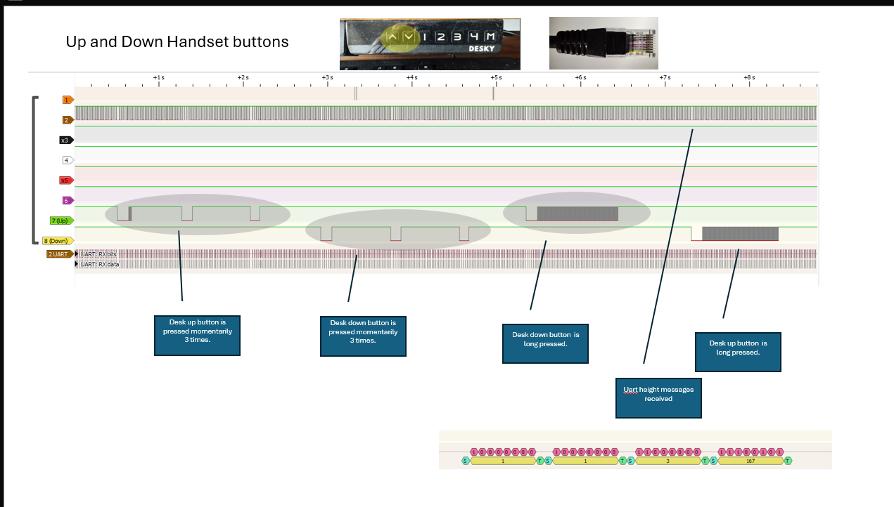
I’m just going to dump some signal sniffing in a few posts to help collate some content to work through some things with ssieb on Discord. A bit easier for larger chunks of text here.

Intial summary (and confirmation of earlier Phord findings).

Button press simulations for ssieb.

substitutions:
# Name                               GPIO     | Wire   | Colour | Description 
  W1_Memory_ControlWire_write_pin:   GPIO32  #| Wire 1 | Clear  | "Memory" Control wire
  W2_UART_C2HS_RX_pin:               GPIO33  #| Wire 2 | Brown  | Intercepts uart messages from controller to handset
  W4_WakeRequestHeight_write_pin:    GPIO25  #| Wire 4 | White  | "Wake" wire
  W6_ControlWire_write_pin:          GPIO26  #| Wire 6 | Purple | Control wire
  W7_Up_ControlWire_write_pin:       GPIO27  #| Wire 7 | Green  | "Up" Control wire
  W8_Down_ControlWire_write_pin:     GPIO14  #| Wire 8 | Yellow | "Down" Control wire

output:
  - id: wire_1_clear_memory
    platform: gpio
    pin: ${W1_Memory_ControlWire_write_pin}
    inverted: true
  - id: wire_4_white_wake_request_height
    platform: gpio
    pin: ${W4_WakeRequestHeight_write_pin}
    inverted: true
  - id: wire_6_purple_control
    platform: gpio
    pin: ${W6_ControlWire_write_pin}
    inverted: true
  - id: wire_7_green_up
    platform: gpio
    pin: ${W7_Up_ControlWire_write_pin}
    inverted: true
  - id: wire_8_yellow_down
    platform: gpio
    pin: ${W8_Down_ControlWire_write_pin}
    inverted: true

button:
  - name: "Pulse W1 Clear - Memory"
    id: pulse_wire_1
    platform: template
    on_press:
      then:
        - output.turn_on: wire_1_clear_memory
        - delay: 300ms
        - output.turn_off: wire_1_clear_memory

  - name: "Pulse W4 White - WakeRequestHeight"
    id: pulse_wire_4
    platform: template
    on_press:
      then:
        - output.turn_on: wire_4_white_wake_request_height
        - delay: 300ms
        - output.turn_off: wire_4_white_wake_request_height

  - name: "Pulse W6 Purple - Control"
    id: pulse_wire_6
    platform: template
    on_press:
      then:
        - output.turn_on: wire_6_purple_control
        - delay: 300ms
        - output.turn_off: wire_6_purple_control

  - name: "Pulse W7 Green - Up"
    id: pulse_wire_7
    platform: template
    on_press:
      then:
        - output.turn_on: wire_7_green_up
        - delay: 300ms
        - output.turn_off: wire_7_green_up

  - name: "Pulse W8 Yellow - Down"
    id: pulse_wire_8
    platform: template
    on_press:
      then:
        - output.turn_on: wire_8_yellow_down
        - delay: 300ms
        - output.turn_off: wire_8_yellow_down

  - name: "Simulate Button 1 - W7W8"
    id: simulate_button_1_green_yellow
    platform: template
    on_press:
      then:
        - output.turn_on: wire_7_green_up
        - output.turn_on: wire_8_yellow_down
        - delay: 300ms
        - output.turn_off: wire_8_yellow_down
        - output.turn_off: wire_7_green_up
        
  - name: "Simulate Button 2 - W6"
    id: simulate_button_2_purple
    platform: template
    on_press:
      then:
        - output.turn_on: wire_6_purple_control
        - delay: 300ms
        - output.turn_off: wire_6_purple_control

  - name: "Simulate Button 3 - W6W8"
    id: simulate_button_3_purple_yellow
    platform: template
    on_press:
      then:
        - output.turn_on: wire_6_purple_control
        - output.turn_on: wire_8_yellow_down
        - delay: 300ms
        - output.turn_off: wire_8_yellow_down
        - output.turn_off: wire_6_purple_control

  - name: "Simulate Button 4 - W6W7"
    id: simulate_button_4_purple_green
    platform: template
    on_press:
      then:
        - output.turn_on: wire_6_purple_control
        - output.turn_on: wire_7_green_up
        - delay: 300ms
        - output.turn_off: wire_7_green_up
        - output.turn_off: wire_6_purple_control

  - name: "Simulate Button M - W1"
    id: simulate_button_M_clear
    platform: template
    on_press:
      then:
        - output.turn_on: wire_1_clear_memory
        - delay: 300ms
        - output.turn_off: wire_1_clear_memory

Hey

i have a very “dump” JCB35M11B Controller on my desk. Is there also a way to controll this via an ESP? As this don´t have a RJ45 Port i doubt it…

Possibly it uses the same protocol on the integrated board.

You’d need to be willing to do lots of investigation to confirm if it is possible.

You’d need to pull it apart and may need a signal analyser.

The control board would probably have some higher voltages on it so you’d need to be safe with that. It would have a lower voltage side too since it has a usb A port.

1 Like

thank your for your reply but i dont have a signal analyzer to bad but thats ok

1 Like

I was recommended this cheap one and I have been quite happy with it if you are interested in getting one.

I just found this on AliExpress:
AU$12.79 | USB Logic Analyzer 24MHz 8 Channel 24M/seconds Logic Analyzer Debugger For ARM FPGA Logic Analyzer Logic 24M 8CH
https://a.aliexpress.com/_mtF369V

Hi there,

I have now switched over to the new buttons. But I am having the problem, that my desk is only moving for a split second, after pressing the button. I have used the exact setup. How could I fix that?

Thanks a lot for any help on how to do that. :smiley:

EDIT:

I have now fixed it by replacing the 300ms with 30s … no clue why that works, but it does :sweat_smile:

1 Like

Hello together,

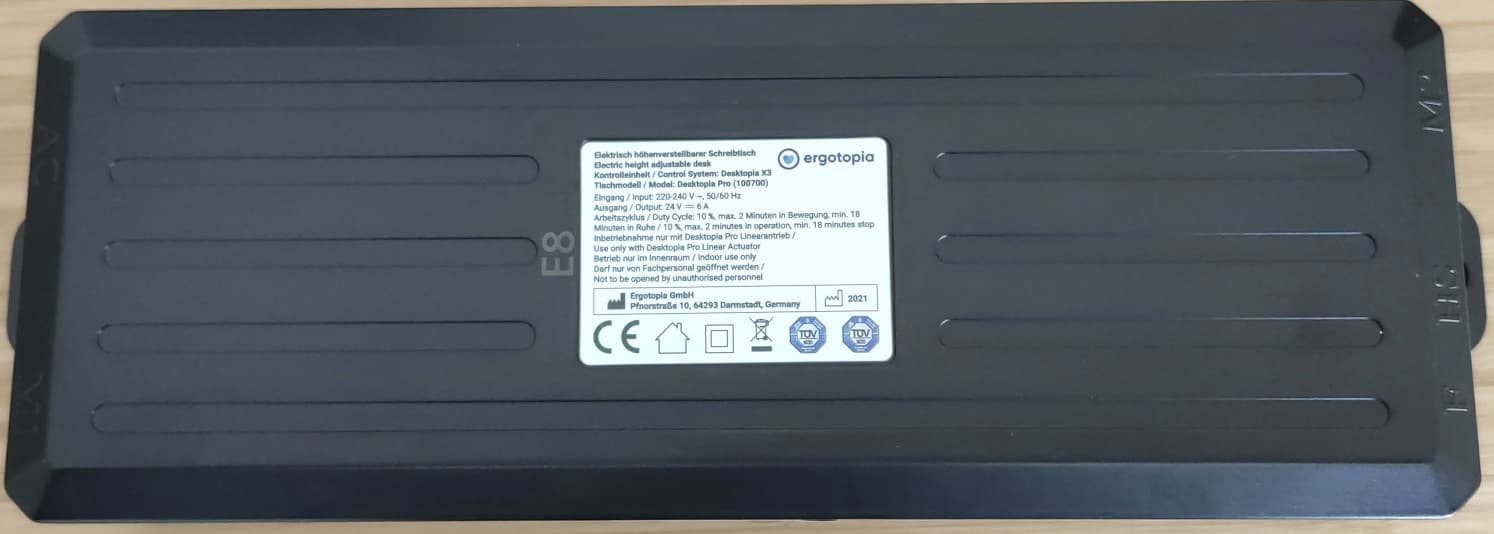
I am using an ergotopia Desktopia Pro X since one week.
I’ve seen the solution from @solution3 using the RJ11 port to get data via an ESP32 to Home Assistant.

Do you know if it’s possible to use the same solution for the Desktopia Pro X? It has an other Frontpanel with only three memory slots but the controller also have a free RJ11 Port.

I know that ergotopia uses this port for their own bluetooth dongle - it’s necessary to connect it to the ergotopia Smartphone App - but I prefer the way to send the data to my Home Assistant.

Thanks a lot in advance!

Best Regards,
Dome

I think there’s a decent chance it is a Jiecang Controller and will work.

I would just build a dongle and give it a go.

Thanks for your quick reply.
That means I cannot crash anything trying it out?

I think it’s a jiecang controller - looks like the pictures above.

I have a Desktopia Pro X myself and only a few days ago built an adapter for the desk’s RJ11/12 port.

This does work to a degree, at least with GitHub - Rocka84/esphome_components, the limitation being that you won’t be able to read the current height or limits.
That limits (no pun intended) the functionality a bit.

I wasn’t aware of a bluetooth dongle from Ergotopia. Do you happen to have one?

The “RJ12 approach” should be quite safe to try. It should be fine but it’s always at your own risk.

Quite possibly this can be debugged. First step is to see if you can see some uart messages.

A lot of the time it is just something pretty basic to do with wiring or pin configuration.

Hi,
thanks for the response!
I’ve already tried enabling debug outputs with the following configuration:

uart:
  id: uart_bus
  tx_pin: TX
  rx_pin: RX
  baud_rate: 9600
  debug:
    direction: BOTH
    dummy_receiver: true
    after:
      delimiter: [0x7E]
      # timeout: 5ms
    sequence:
        # Use mulcmu's method for reading uart without a custome component: https://community.home-assistant.io/t/how-to-uart-read-without-custom-component/491950?u=mahko_mahko
      - lambda: |-
          UARTDebug::log_int(direction, bytes, ',');
          UARTDebug::log_hex(direction, bytes, ',');

And I do see outgoing messages, but no incoming ones.

In fact, I want to try adding a logic analyzer to the setup later today.

1 Like

Hmm right. Did you try another pin for Rx?

Just finished the recording.


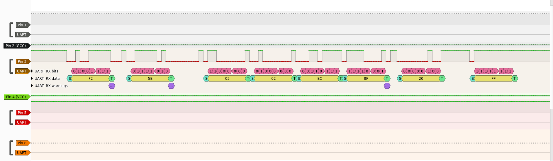
(captured at 20 kHz, UART decoders set to decode 9600 8N1).

Pin 3 is the same one that’s connected to my ESP32.
(That’s without the ESP connected)

I don’t think I’ve accidentally swapped RX and TX, else I wouldn’t expect to be able to control the table.
And I do have continuity from the third pin on the plug to the pad on the ESP32 board I’m using.

Does that look correct? I’m having some doubts about the 8N1 part (looks like the desk sends no stop bits at all), but I think that’s what the UART in esphome uses with my configuration?

If so, I’m wondering whether the framing errors may be what throws off the ESP. Can one get that kind of information out of esphome as well?

Here I’ve connected the logic analyzer directly to the pins of the ESP32-C3.


So the desk is definitely sending data after starting movement via the ESP.

I suspect the issue to actually be a configuration problem with the ESP or it indeed expecting stop bits.
I might try using it with software UART.

1 Like

Hmm right. Are you getting that as a repeating structure (when you move the desk).
As-in do you always get 8 bytes that start with F2 and end with FF?

Edit: I see above yes.

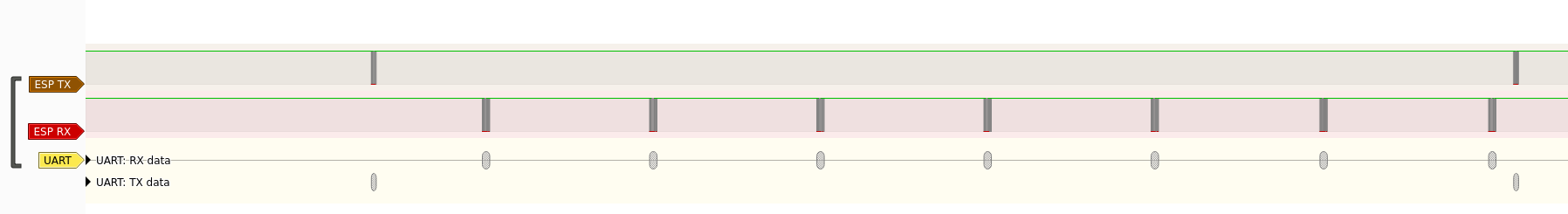
Can you pick up some messages on the ESP like this? Maybe try tweaking:

    after:
      bytes: 8 # or 9 

It’s good you’ve found some uart messages, now you need to try to find a stable repeating pattern. I am a bit rooky with uart so I don’t know about framing errors. I would make sure you are sharing ground between all devices (I think).

Did you try another GPIO for your Rx on esp yet?