Hi all,
I want to tell you about my personal experience of modernizing cat feeders from PetKit - Fresh Element Mini. And I hope that my rough English will not make too much problem for you to read this post ![]()
Background
Spoiler
I have 2 cats at my place. My wife and I sometimes go to our relatives for several days. And we have a feeding problem: cats compete with each other in eating food, as a result, if you pour a lot of food, they eat as much as possible at a time, and then return the excess along with the wool.
About a year ago, it was decided to try to get out of the situation with an automatic feeder.

With this feeder you can set up a profile for several cats, taking into account the calorie content of the feed, etc. It has a nice design, convenient application with notifications and remote control. There is also a button for manual feed dispensing. When pressed and held, the feed is poured into the bowl. It is worth letting go - the feeder stops.
In general, I am more than satisfied with the feeder. It works as expected. If the Internet is gone, it continues to dispense feed on a schedule.
But there is a problem: Sometimes the feeder signals a loss of connection with the PetKit servers. In this case, the feeder usually just continues to work properly.
During the year of owning this device, I had a situation 2 times when the feeder went offline and the feeding did not happen. Although when you press the manual feed button, the feed dispensing. So, apparently, the data on the feeding schedule was lost. To fix it, you had to reset the settings of the feeder, connect it via a mobile HotSpot, wait for a successful connection and then reset it again and connect to your home WiFi.
And if these steps 2 times a year do not cause any particular problems, then the likelihood of leaving cats without food for 3-5 days disappoints me. And the saddest thing is that you can’t do anything until you get home.
In general, a cardinal decision was made to change something. But what? The feeder as whole suits, minus annoying mistakes 2 times a year. Other feeders have the same functionality, but the problems are most likely exactly the same.
Now, if I could somehow connect it to the Home Assistant and locally send a signal to dispense food … And then BAM - I found the next article: Petoneer Nutri Smart Pet Feeder where a person reviews a similar device and then reflashes it WiFi module TYWE3S (which is based on ESP8266) and transfers full control of the feeder to its Home Assistant server.
Well, and how am I worse?
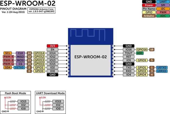
I found a video of the disassembling of the PetKit feeder (by the way, here it is: YouTube) and realized that the situation is similar. A similar antenna is based on the ESP8266. In my case, it was the ESP-WROOM-02 module. In general, you can just replace the firmware and …
And completely lose all available opportunities, permanently deprive the feeder of communication with the PetKit servers, deprive yourself of control via a mobile application, portioned food delivery to cats, etc. turning a smart device into a shadow of itself. It will just simulate a manual push of the feed button based on a command from HA and that’s it.
It won’t work that way. It was decided that the feeder should remain fully functional. The option with a re-flashing of ESP-WROOM-02 has disappeared. But what prevents us from putting your ESP8266 internally? We can power it from any suitable power supply on the mainboard and simulating a manual button press in the same way?
Preparation
Required:
- Phillips screwdriver
- Plastic spatula/spudger
- ESP8266 (in my case, this is NodeMCU by Lolin)
- Soldering iron
- Wires
- 2pin + 4pin or 6pin connectors (optional)
- bravery
- Stupidity
Disassemble
- Take the feeder, disconnect the bowl

- At the bottom, unscrew 2 screws: the 1st holds the backup power compartment cover, the 2nd holds the back wall

- Using a spudger, carefully detach the back half from the front and disconnect the cable. This process is well illustrated in the video: YouTube

- Remove the gray casing covering the mainboard and reveal the object of torture

-
We remember where which wires go, just in case we take a photo and write it down in a notebook
-
Gently detach the feed lid. It is secured with two pins on a leg with rubberized ears

- Unscrew 4 more screws from the bottom and we can take out the gray box with the engine. We remove it carefully

- You are gorgeous

Inventory
- Optocoupler sensor for the condition of the cover (which was in step 6 of the analysis).

- Optocoupler sensor of the condition of the motor (reads interruptions caused by the comb).

- Motor.
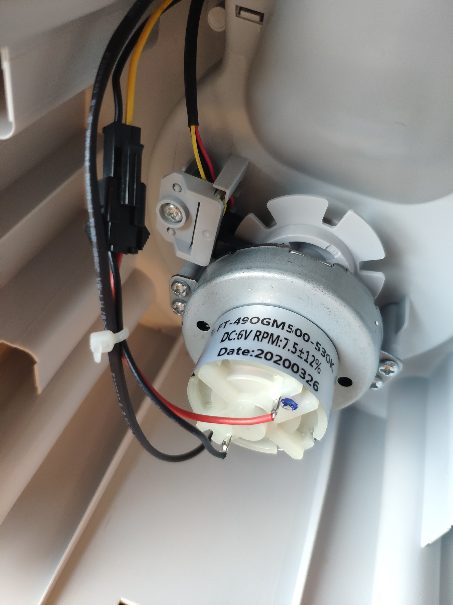
- Optical feed level sensor (we partially removed it together with the rear wall).

- The mainboard itself.

- The rest of the junk (buzzer, alarm diode, cover opening motor).
Connection
After a small investigation of the mainboard I managed to find out where to solder in order to achieve success:
- Power supply (3.3v or 6v depending on your controller)
- GND
- Manual feed - 5th leg (GPIO13)
- Optical feed level sensor
- Optocoupler of the state of the food supply cover
- Optocoupler of the impeller of the motor

On the side of my Chinese NodeMCU, I soldered like this:
- Power - Vin (on this pin the LM1117 regulator is set to 3.3v).
- Earth - GND
- Optical feed level sensor - D0
- Optocoupler of the state of the lid of the food supply - D1
- Optocoupler of the status of the lid of the food supply - D2
- Feed button - D3

The photo shows that while I was attaching the connector, I mixed up the colors. Green turned red, yellow turned orange, etc. But this is not important, although it is very confusing. Fortunately, the dero connector can only be inserted in one position.
Firmware
It’s time to flash NodeMCU using ESPHome. Otherwise, after collection, access will be somewhat limited.
Configuration in details:
1. Optical feed level sensor - D0
 binary_sensor:
  - platform: gpio
    name: "PetKit Food level state"
    device_class: problem
    pin:
      number: D0
      inverted: true
    filters:
      - delayed_off: 120000ms
The signal is inverted. If there is not enough feed, it is interrupted for a fraction of a second every 10 seconds until you add food. As a result, I had to add an inversion and make a delayed_off for 20 seconds. If the signal is interrupted, the sensor signals a lack of feed and remains in this position for 20 seconds. If during this time it receives another signal interrupt, the counter is reset to zero. If there is no signal interruption for more than 20 seconds, the feed has been filled up.
2. Optocoupler of the state of the lid of the food supply - D1
  - platform: gpio
    name: "PetKit Cap state"
    pin:
      number: D1
      inverted: true
    filters:
      - delayed_on_off: 100ms
      - delayed_off: 2000ms
The signal is inverted. When the lid is closed, an interrupt occurs once per second. The feeder is actively checking to see if someone is trying to break it. I cannot explain it otherwise. I added delayed_on_off for 100 milliseconds to ignore short changes in signal to not clutter up the history. Now it the signal will be ignored as long as it is shorter than 100 milliseconds. With a real trigger, the interrupt will last for a few seconds - it means that the lid is open.
UPD: delayed_off for 2 seconds added to avoid bouncing state during cap opening.
3. Optocoupler of the state of the lid of the food supply - D2
  - platform: gpio
    name: "PetKit Motor state"
    device_class: moving
    pin:
      number: D2
      inverted: true
    filters:
      - delayed_on_off: 100ms
      - delayed_off: 2000ms
The signal is inverted. The optocoupler does not send any signal changes until the motor is moving. During motor rotating the impeller of the motor passes through the Optocoupler approximately once per second. The signal is intermittent. To avoid this, a 2-second delay has been added for the response to the signal off. Also, I added delayed_on_off for 100 milliseconds just in case. It’s not really needed there.
4. Feed button (sensor) - D3
  - platform: gpio
    name: "PetKit Feed button state"
    pin:
      number: D3
      allow_other_uses: true
      inverted: true
Well, everything is simple, the signal is inverse, we read the manual pressing of the button. Just because we can.
5. Feed button (switch) - D3
switch:
  - platform: gpio
    pin:
      number: D3
      allow_other_uses: true
      inverted: true
    id: relay
    name: "PetKit Feed button"
    icon: "mdi:shaker"
    on_turn_on:
      #2000    4g
      #4000    8g
      #20000ms 50g
    - delay: 4000ms #50g
    - switch.turn_off: relay
Actually, the highlight of the program is the imitation of manually pressing the button. The same inverted signal. When you press the button, you need to hold it, otherwise, the feeder will ignore it as an accidental pressing. Pressing for 2 seconds gives 4 grams of feed, 4 seconds - 8 grams, 20 seconds - 50 grams.
The final configuration file looks like this:
esphome:
  name: petkit-feeder-esp8266
  platform: ESP8266
  board: nodemcuv2

# Enable logging
logger:

# Enable Home Assistant API
api:

ota:
  password: *********************************

wifi:
  ssid: "***************************"
  password: "***********************"

#uncomment next 2 lines if you want to have web server on your esp8266
#web_server:
#  port: 80

binary_sensor:
  - platform: gpio
    name: "PetKit Food level state"
    device_class: problem
    pin:
      number: D0
      inverted: true
    filters:
      - delayed_off: 20000ms

  - platform: gpio
    name: "PetKit Cap state"
    device_class: opening
    pin:
      number: D1
      inverted: true
    filters:
      - delayed_on_off: 100ms
      - delayed_off: 2000ms

  - platform: gpio
    name: "PetKit Motor state"
    device_class: moving
    pin:
      number: D2
      inverted: true
    filters:
      - delayed_on_off: 100ms
      - delayed_off: 2000ms

  - platform: gpio
    name: "PetKit Feed button state"
    pin:
      number: D3
      allow_other_uses: true
      inverted: true

switch:
  - platform: gpio
    pin:
      number: D3
      allow_other_uses: true
      inverted: true
    id: relay
    name: "PetKit Feed button"
    icon: "mdi:shaker"
    on_turn_on:
      #2000    4g
      #4000    8g
      #20000ms 50g
    - delay: 4000ms
    - switch.turn_off: relay
If you want to send grams directly to the ESP - read Drealine message: Link
Assembly
I carefully glued my spy board next to the engine using hot-melt glue. Not elegant but should be enough.

The wire could be pulled through the native technological hole, but we are not looking for easy ways. Therefore, it was decided that it was necessary to dig out a hole with a broken clerical knife.

We screw the mainboard into place, connect all the wires in the reverse order + our spy board.

We close it with a decorative casing. I had to cut it slightly, otherwise, the wire stretching to the new “technological” hole was slightly pinched. By the way about it - I also glued it over, just because I can.


Result
Actually from the outside nothing has changed at all.
However, now the smart home finds the petkit-feeder-esp8266 device in the local WiFi network and allows you to feed cats or find out the current status of the device without any problems. You can save the log of events associated with the feeder in the history and be able to analyze whether the feeding was completed.

Now, in case of a glitch with a fallen-off server and not-fed cats will appear again I can set up an alert on the phone and/or press the feed button via automation. Like a safety system.

In the end, the project goal was achieved. The feeder received a couple of new features and did not lose any of its function and/or good looks. And only a hastily made technological hole gives out the hand of the master.
In case if you will have any questions - don’t hesitate to ask.
Or if you will have any ideas how this project can be improved - welcome to discussion.
Thank you.