I haven’t tried casting the camera, so I can’t comment. However, if direct casting does not work, I see no reason why casting a view that includes a doorbell camera feed with Home Assistant Cast wouldn’t work.
This looks amazing, hats off to you for the work you’ve put in. Currently printing the doorbell casing now 
Is there a separate design doc for the lens insert? Only the link is for the doorbell case from what i can see. Or is it ‘hiding’ somewhere on that page?
Thanks
Thanks, @jampez77 ! Good luck your project. Your should see a separate tab at the bottom of the OnShape window for the lens insert.
I knew it would be staring me in the face. Happens all the time and i never learn haha. Thank you!
Ideally, one could keep their existing 12VAC transformer, bells, and wiring in place. The problem is making use of the 12VAC to power an esp… especially that the 12VAC will see large fluctuations as the bells draw current when active (so no DC regulators, and trabsformers are usually 2A rated only). I imagine any setup that can do this, would need a very large cap to store power to handle the spikey esp currents and momentary voltage dips. Anyhow, doable, but I don’t think it as easy as it seems at first glance. This is why I haven’t added an esp to my bell yet… still using an ip camera and a hall sensor to detect bell current directly. 
Edit… I am referring to doorbell systems found in the usa… not sure if other places use DC for bell circuits but we don’t here.
I should have thought of this earlier but how have you mounted it to your wall? I see no screw holes in the case itself.
And have you printed with PLA? if so, how’s that handled the outdoors?
I used sealant. It holds well and makes for a clean look. I didn’t want to make more holes in the door frame than necessary.
Yes, PLA. My doorbell is sheltered from the elements, but is does get first sun for part of the day. An early version of the doorbell back when I was using a Pi Zero warped last summer. Since I increased the thickness of the walls, it appears to be holding up well.
Understood. I guess the other option could be to reuse just the AC wiring for DC and go wireless for the bells.
I expect that you’ll get a much higher quality image/video with your IP camera. I just don’t have the space. I do also have an Arlo camera at the front door, but it basically points down at the top of the person’s head. So, it’s not very useful once they’ve rung the bell. And, snapshot requests through the cloud aren’t fast enough to rely on ones triggered by a motion sensor as the person approaches.
So my parts have arrived
First question…how did you flash the ESP32-Cam? I’ve tried in a few ways, GPIO0 to Ground while turning on, pressing the button. They all timeout. From what I can see i’ve got the wired up correctly as per this diagram:
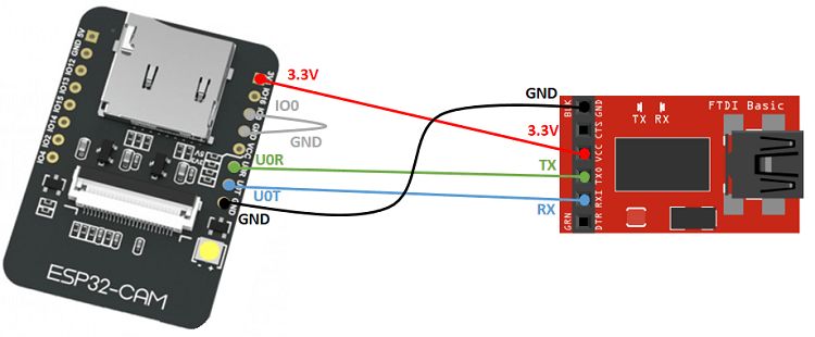
That seems correct. I just put a jumper on the IO0 and GND pins while flashing. Like your picture, but not just only while booting.
I did the same as @francisp, also leaving IO0 and GND jumpered for the whole time it was flashing. I don’t think that’s strictly necessary, but it helps to avoid missing the magic moment on boot.
Awesome project! Thanks for sharing.
1 Like
Sorted it! I have a dodgy wire! thanks guys.
1 Like
any way to get the front acrylic as an stl file? since i still want to tinker with it a bit to maybe add a pir sensor and/or mic i was going to print the front acrylic from pla. other than that great project!
Thanks. I don’t have a cad version of the front insert with the speaker grill, but here’s cad of the insert without. You could tweak it in OnShape more easily than if you started with STL. If you prefer, OnShape can export it as STL.
You could instead convert the EPS insert file to DWG online–or to whatever your cad application can import. There are several variants in the EPS file.
Lastly, if your doorbell is going to be in direct sunlight most of the time, you might have a problem with the insert deforming if it’s in PLA. I had a 1.5mm (thinner than the acrylic) PLA insert in one of the many early prototypes. It deformed after about a month in British “sun”.
Thank you 
Sorry to pester again.
I’m a complete newbie with ESPHome and I’m having issues getting the doorbell to the WiFi.
It comes online in ESPHome for a brief moment, only to change to ‘not responding’ and then back to ‘offline’.
The logs just look to show repeated attempts at connecting to the WiFi network:
INFO Connecting to 192.168.86.28:6053 (192.168.86.28) WARNING Initial connection failed. The ESP might not be connected to WiFi yet (Error connecting to 192.168.86.28: timed out). Re-Trying in 1 seconds
Any help from anyone would be greatly appreciated.
It’s almost certainly a question of IP address. Your ESP32 Cam is probably never coming online. When it says…
INFO Connecting to 192.168.86.28:6053 (192.168.86.28) WARNING Initial connection failed. The ESP might not be connected to WiFi yet (Error connecting to 192.168.86.28: timed out). Re-Trying in 1 seconds
…that just means that ESPHome is TRYING to connect, not that it has connected and then drops.
192.168.86.xxx is probably not correct for your gateway/router and the ESP32 Cam itself. If you’d normally access your router settings at 192.168.0.1, for example, that’s the IP address that you should put in the substitutions section for wifigateway. You’ll also need to change staticip to the IP address that your router first assigns to the ESP32 Cam.
You then upload the modified configuration file over USB again. You can’t use OTA since the ESP32 Cam is not online.
Steps:
- Modify the substitution and WiFi sections of the ESPHome config as in the examples below.
- Upload the edited config over USB.
- Watch the ESPHome log and note the IP address that gets assigned to the ESP32 Cam when it connects.
- Put that address in the config under
static_ipin the substitution section of the config files and uncomment the themanual_iplines in the WiFi section. - Upload the config file again. You will be able to use OTA now.
Changes to the substitution section:
# Substitutions
substitutions:
  board_platform: ESP32
  board_type: esp32cam
  devicename: doorbell
  hostname: doorbell
  buttonname: doorbell_button
  devicestatusname: doorbell_status
  staticip: 192.168.XXX.XXX # Change to the IP address that your router assigns on first connection
      # At the same time, uncomment manual_ip and the three lines below it in the WiFI section below
  apssid: esphome_doorbell
  wifigateway: 192.168.XXX.XXX # Change to your actual gateway address
      # It's possibly 192.168.0.1 or 192.168.1.1
  subnet: 255.255.255.0
  # esp32 cam
  buttonlight: doorbell_button_light
  buttonlightpin: GPIO13
  statuslight: doorbell_status_light
  statuslightpin: GPIO33
  flashlightpin: GPIO4
  buttonpin: GPIO12
  # dfplayer
  df_tx_pin: GPIO14
  df_rx_pin: GPIO15
Changes to the WiFI section:
# Enable WiFi
wifi:
  networks:
  - ssid: !secret wifi_ssid
    password: !secret wifi_pwd
  - ssid: !secret wifi_ssid_backup
    password: !secret wifi_pwd_backup
  # manual_ip:
  #  static_ip: $staticip
  #  gateway: $wifigateway
  #  subnet: $subnet
  ap: #Settings for captive portal
    ssid: $apssid
    password: !secret esphome_appassword
captive_portal: # AP in case WiFi connection fails
2 Likes
Thank you so much!!!
That’s it! i’m up and running on the software side of things now. Just waiting for the button to arrive.
1 Like
Thanks so much for this @ronschaeffer! It inspired me to bite the bullet and try this for myself Meanwhile I’ve got most of the project up and running (I’m still waiting for my LED-ring button, but I’ve been testing everything with a momentary button I had laying around).
Now for the the tricky (and mostly WAF-influenced) bit: the doorbell housing… I have a few questions about that:
- In your Onshape project you have two camera surrounds, which one should I print in combination with the acrylic front insert?
- Do you use any kind of lens cover to protect the camera? I see that you mention a lens insert, but I don’t see a link to an actual lens

- How do you mount the ESP32-cam in the housing? Do you maybe have a picture of how you did this?
Thanks again for this great project!
1 Like