Doorbell - Aqara? - Reolink? - transformer and chime?

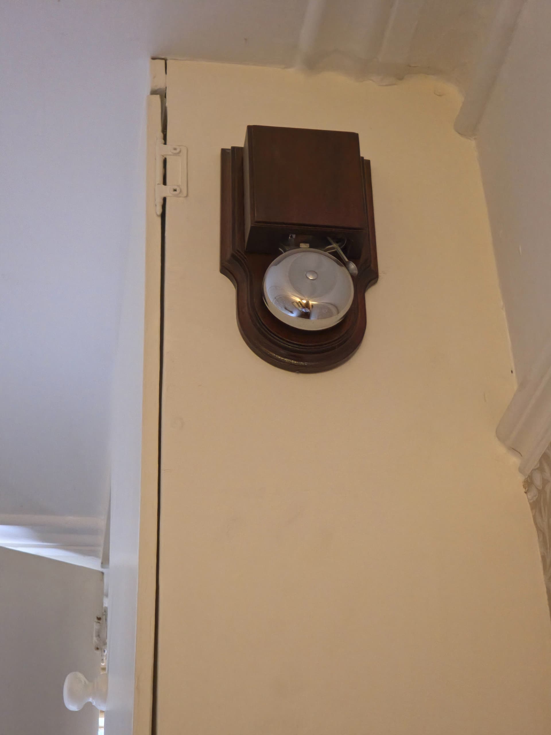
My old doorbell (basic press-button and electromechanical bell) has just failed again. The electromechanical bell and button was new in 2015 and the transformer new earlier this year because the previous one failed. Testing yesterday, there were 0v across both terminals of the press-button when the button was not pressed, suggesting that the transformer has failed again. I suspect that the electromechanical bell may be drawing too many amps.

I thought that I should take the opportunity to upgrade to a smart doorbell that works with HomeAssistant. The research that I have done gives a somewhat incomplete and difficult to understand impression of what actually works well, and it would be very helpful if anyone had any insight into the various issues that arise from such information as is available as applied to my particular situation.

The position is as follows:

  • I live in the UK (so 230v mains);
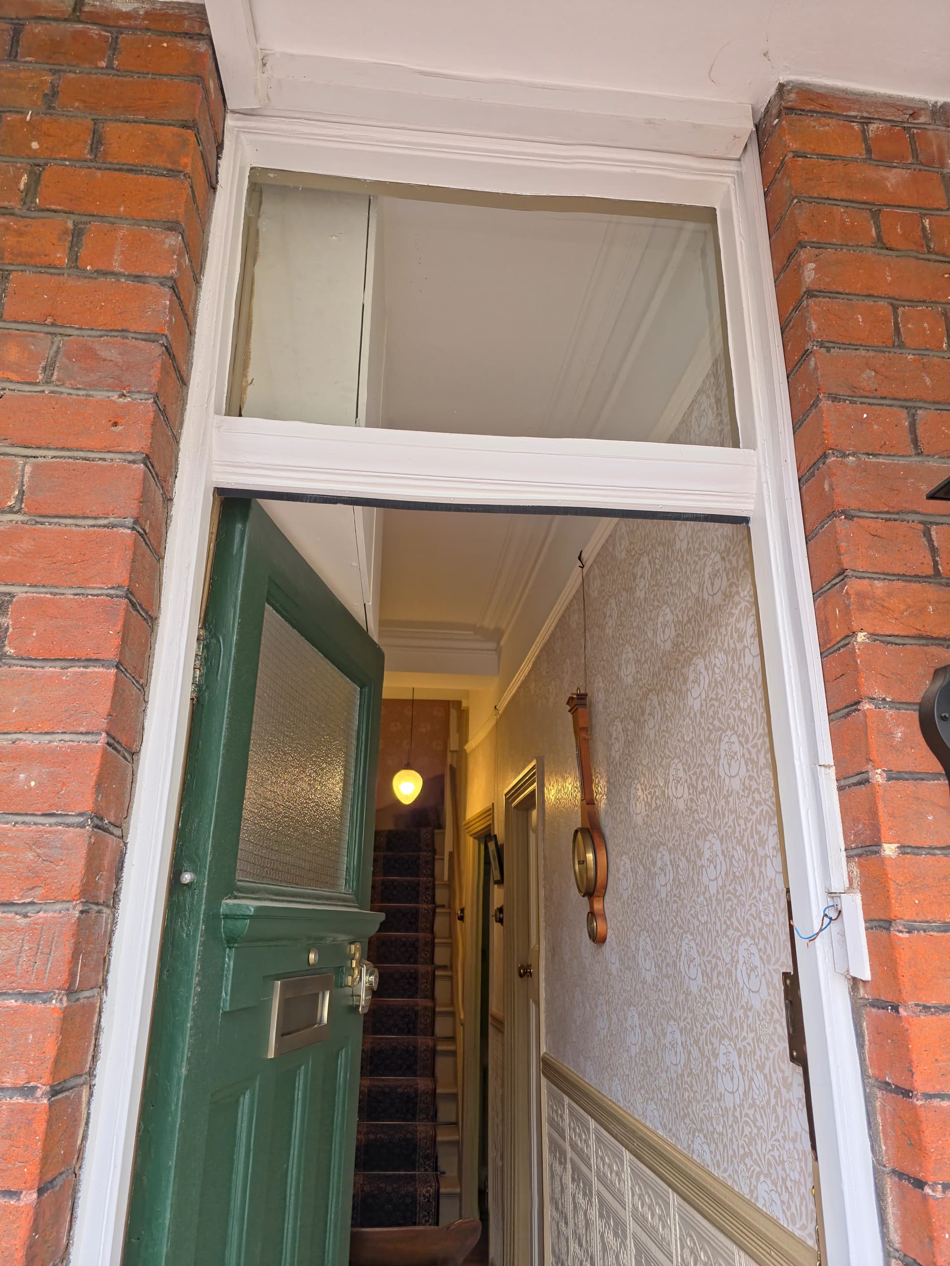
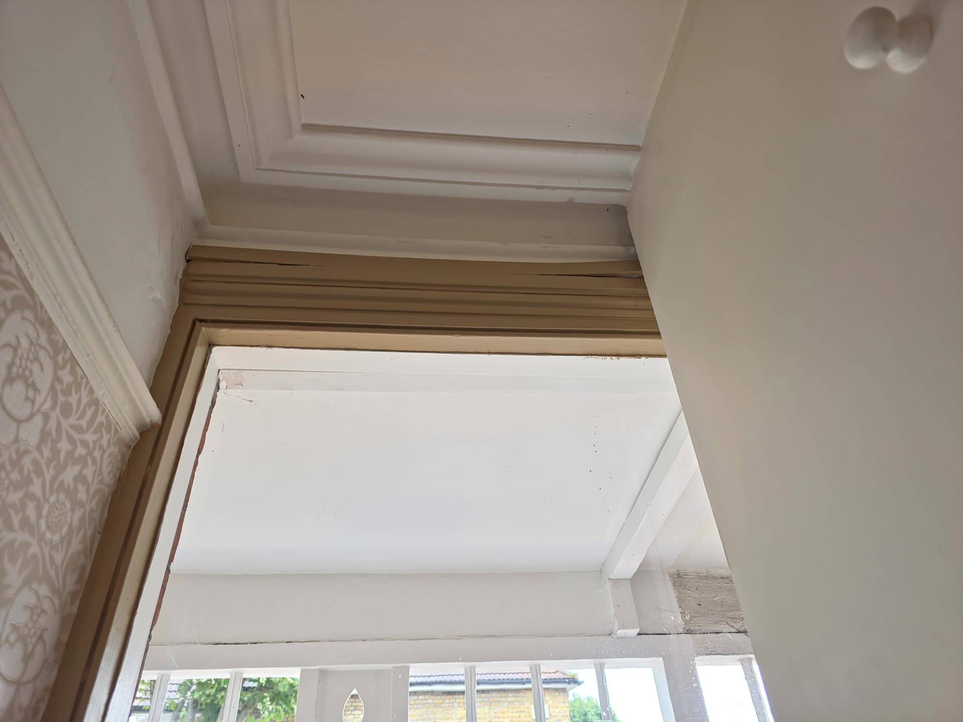
  • there is a wire run to the outside from the doorbell transformer to the bell press;
  • the current (new) doorbell transformer is probably not working (see above);
  • the physical space to put a bell press by my door where the current wire run ends is very, very limited, and any camera sized doorbell press would have to be in a slightly different place with a longer wiring run;
  • I live in a terraced house in London directly facing the street - because of oppressive “privacy” laws, I will need to a system that enables privacy masking on any recorded footage to mask the street and the neighbour’s porch;
  • I do not have any HomeKit equipment;
  • I have a Thread border router dongle connected to the USB port in my HomeAssistant;
  • I have several Synology NAS devices for possible recording; and
  • I have no ethernet anywhere near my front door and it is not practical for me to install PoE to near my front door.

Requirements are as follows:

  • can be fully integrated in the long-term (and immediately) with HomeAssistant with 100% local control and no dependancy on any out-of-house cloud services;
  • video recordings stored locally but not in the outside bell press (or alternatively in the outside bell press and in the house, e.g. on one of the Synology drives);
  • any recordings be periodically overwritten with new recordings so as not to take infinite space on my NAS (if used), but with the ability selectively to save specific footage indefinitely;
  • privacy masking features as above;
  • very high reliability;
  • no real risk of not being able to set it up to work properly and with no cloud dependency within a reasonable time;
  • if possible/practical, able to be used with my existing mechanical chime (perhaps with a Matter relay and added resistor to prevent it burning out another transformer); and
  • being able to know whether somebody is at my door if I am in my shed, where I cannot hear my current mechanical chime (I suspect that most video doorbells would meet this requirement).

Potential issues (on which guidance would be appreciated):

  • Matter does not support video streams, so all video doorbell integrations require some workaround that makes things more complex - the forum posts discussing these all seem to assume deep prior knowledge of the components of these workarounds (“Frigate”?) which makes them hard to follow;
  • the only Matter relays that I have been able to find will only work with full mains voltage on the outputs, so to use the existing mechanical chime, I will need a second, dedicated transformer for this;
  • I will need to get an electrician to install all this, but have no way of knowing in advance what electrician will be able to work with this type of system and deal with things like Matter relays effectively; and
  • the doorbells that I have seen most often mentioned working with HomeAssistant are the Reolink and the Aquara G4 and G410, but some people report persistent WiFi problems with the Reolink (frequent brief disconnexions, and needing to set up the whole integration again after each one) and great difficulty in setting up the Aqara (most of which instructions assume that the user has an Apple HomeKit, which I do not have), and it is very difficult to make sense of which, if either, of these types is really workable.

Any assistance in navigating the above complexities would be most welcome. Thank you.

Visual inspection time. Take pictures and post them if you can.

What is the make, model, voltage and amperage rating on your bell transformer? Often they are 24volts AC, at 1A on the secondary.

Same details please for the ratings for your bell? If not power markings, at least the make and model would help.

Is it mechanical with a traditional clanger and round bell, or electronically generated sound? When it rings, are there sparks from the vibrating contacts, and are the contacts black and pitted?

Is the transformer and bell simply connected directly via the switch, or do you have a relay in the circuit as well?

What happened to the old transformer? Was it zapped from a power surge? Old age? Exposure to the elements, moisture, heat? Fire? Did you replace it with an identical one, one of the same rating, or one of higher rating ( amps as well as maybe volts)?

Do you have thin wires going to your door bell? Two, three, four, or more? Twisted pair? Shielded coaxial cable? Can you photo them alongside some readily associated object like a pencil or tape measure to get an approximate idea of the current capacity and thickness. Is the material the doorbell is attached to metal or timber, possibly allowing for another ground return.

Are the wires encased in plastic or metal conduit or channelling? How do they get to the push button? Is there just a hole in brickwork where the wires emerge from inside the wall cavity? Are they hidden behind an architrave the electrician can easily remove and replace? Inside aluminium channelling for your door frame? Run from the ceiling or floor via a discrete conduit to waist level? Do you have easy access to the ceiling space and underfloor to be able to check where the wires run? If you were to run new cables, how easy would it be to hide them to achieve a professional finish and pleasant for visitors to observe.

How long is the wire run from the front door press to somewhere else you can get to the wires? Does it navigate any bends, corners, or junctions so it cannot be pulled out easily (please don’t pull it out to find out, just guess based on your observations)

Your electrician may be able to gingerly use the existing cable as a draw string to pull through some heavy duty draw string, and use that to pull some more suitable cable such as twisted pair, multicore coax/power security cable, or even just low voltage to power a WiFi connected camera.

You could also consider running AC power and signal down the same wires using a form of multiplexer. Even use your existing transformer to power it. Your resulting video may be poor quality due to bandwidth limitations, but for old buildings that have historic overlays and any modifications to the facade is expressly forbidden, that may be the only option available.

What is the distance from your doorbell to your router, and shed as well? Do you have reliable internet via WiFi to the shed? To the front door?

I’m asking as push-button doorbells are one of those things that very rarely break down, doing decades of reliable operation. Something is amiss, and you need to find what it is before committing to an expensive workaround that may not fix the underlying issue.

Your press button may be shorted, blowing a fuse somewhere, including a safety one internal to your transformer which may be rated for intermittent use at the specified current or the doorbell may be pulling too much current due to spider nests or other vermin inside the solenoid casing, or rust may have bridged the contacts in the bell that vibrate to cause the bell to ring. Put a current meter in series (in line, not across the contacts as you have done) with the doorbell set to an AC range higher than your transformer, and press the button. Any power flow? How many amps/milliamps? Test the voltage across your transformer windings with your meter set to 250volts AC or more. What does it say, both primary (often brown/blue or red/black) and secondary (often both red or yellow) sides? Any visible fuses near the transformer? Do they look intact, or dark and burnt out inside the glass cylinder portion?

Once you can verify what is there, you can explore what options are viable. Your requirements are achievable, but the cost can vary widely based on what options are feasible.

1 Like

Thank you for that detailed response - that is very helpful. I will have to reply in full when I have more time.

One thing occurs to me, though, which is that I assumed that the existing doorbell transformer was DC when it might well be AC, and therefore used the DC volts setting on my multimeter to test it. I will try again on the AC setting and post the results.

Thank you again.

I have now had time to look into this a little more. I attach some pictures of the doorbell, wiring and transformer.

First of all, the transformer is indeed an AC transformer, so my earlier attempts to measure voltage across the two wires from the now removed doorbell press were invalid. Measuring again with the AC setting with the transformer turned on, I get a measured voltage of anything between about 1v and 30v - the voltage seems to wander. I suspect that that is because the amount of voltage being sunk by the bell is wondering rather than that the amount of voltage put out by the transformer is wondering, although it could in principle be either as both are essentially just coils. Touching the two wires together does not result in the bell ringing as it should.

I will now try to answer some of the questions.

What is the make, model, voltage and amperage rating on your bell transformer? Often they are 24volts AC, at 1A on the secondary.

The transformer is pictured above - it was fitted by an electrician who also procured it, so I do not know details beyond what can be seen in the photograph. It appears to have three different windings from which the bell can be tapped: one at 8v, one at 12v and one at 24v.

Same details please for the ratings for your bell? If not power markings, at least the make and model would help.

The bell is described in the small manual as an “Imperial London Bell”. It requires 8-12V AC and 1A.

Given the voltage findings above, I wonder whether the electrician who installed the transformer incorrectly wired the bell to the 24V windings thus overvolting and eventually destroying it?

Is it mechanical with a traditional clanger and round bell, or electronically generated sound? When it rings, are there sparks from the vibrating contacts, and are the contacts black and pitted?

The bell itself is shown in the pictures and is an electromechanical bell. It does not ring, so I cannot say whether there are sparks visible when it rings.

Is the transformer and bell simply connected directly via the switch, or do you have a relay in the circuit as well?

There is no relay in the circuit. The transformer is connected to the bell and the switch.

What happened to the old transformer? Was it zapped from a power surge? Old age? Exposure to the elements, moisture, heat? Fire? Did you replace it with an identical one, one of the same rating, or one of higher rating ( amps as well as maybe volts)?

I do not know why the old transformer failed - I was told that it was not working and it was replaced with a new one by the electrician. I did not specify either the old or the new transformer, but the old transformer was smaller and not of the same type.

Do you have thin wires going to your door belll? Two, three, four, or more? Twisted pair? Shielded coaxial cable? Can you photo them alongside some readily associated object like a pencil or tape measure to get an approximate idea of the current capacity and thickness. Is the material the doorbell is attached to metal or timber, possibly allowing for another ground return.

The wires going to my bell and bell press are either 5A or 3A rated mains lighting cable, multi-stranded copper with blue and brown primary insulation and fabric secondary insulation, intended to give a vintage appearance as is often used in older light fittings. This was spare wire from when I had my ceiling lights re-fitted when the house was refurbished in 2015. They are a twisted pair.

Are the wires encased in plastic or metal conduit or channelling? How do they get to the push button? Is there just a hole in brickwork where the wires emerge from inside the wall cavity? Are they hidden behind an architrave the electrician can easily remove and replace? Inside aluminium channelling for your door frame? Run from the ceiling or floor via a discrete conduit to waist level? Do you have easy access to the ceiling space and underfloor to be able to check where the wires run? If you were to run new cables, how easy would it be to hide them to achieve a professional finish and pleasant for visitors to observe.

The wires are encased in plastic channelling inside and out as shown in the pictures. Inside, the channelling is discretely above the doorframe. It is sadly less discreet outside. I should prefer something more discreet outside, but, as you can see from the pictures, space is very limited. I am not sure how these should best be hidden outside.

How long is the wire run from the front door press to somewhere else you can get to the wires? Does it navigate any bends, corners, or junctions so it cannot be pulled out easily (please don’t pull it out to find out, just guess based on your observations)

The run from the bell press to the MCB cabinet (where the doorbell transformer and doorbell are located) is short as can be seen in the photographs.

You could also consider running AC power and signal down the same wires using a form of multiplexer. Even use your existung transformer to power it. Your resulting video may be poor quality due to bandwidth limitations, but for old buildings that have historic overlays and any modifications to the facade is expressly forbidden, that may be the only option available.

I do not know whether any of the doorbells that integrate well with HomeAssistant are capable of this multiplexing. Is this better than WiFi? I am not in a conservation area, but am very, very keen indeed to avoid any surface wiring in the house. There is no ethernet to or particularly near the MCB cabinet.

What is the distance from your doirbell to your router, and shed as well? Do you have reliable intenet via WiFi to the shed? To the front door?

The doorbell/front door are about 4-5m from the router. The shed is in the back garden and is perhaps 10-15m away from the router in the opposite direction. The shed has its own WiFi mesh router, though, with ethernet backhaul.

Put a current meter in series (in line, not across the contacts as you have done) with the doorbell set to an AC range higher than your transformer, and press the button. Any power flow? How many amps/milliamps? Test the voltage across your transformer windings with your meter set to 250volts AC or more. What does it say, both primary (often brown/blue or red/black) and seconday (often both red or yellow) sides? Any visible fuses near the transformer? Do they look intact, or dark and burnt out inside the glass cylinder portion?

I think that my multimeter only does current in DC - at least, that is what is markings suggest. I did connect this between the terminals of the bell press (as this is the path for the current: it would flow through the bell press to the bell), but no current was recorded as flowing; but this might be because my multimeter only measures amps DC. I cannot easily access the doorbell transformer to be able to test its outputs other than from the two terminals of the bell press. There are no visible fuses near the transformer.


Thank you again for your very detailed response: it is much appreciated.

Thanks for the photos. Very clear and exactly what is needed to troubleshoot.

That doorbell is in magnificent condition visually and should be kept for authenticity. Inspect the solenoid coil under the cover. If the solenoid is burnt out, pay the few pounds to get it re-wound with new wire, or have the solenoid replaced. Your local antique shop may have a source, or ask a electrical specialist like RS Components or your local TV Repair shop if they can help. It goes well with the wall clock. Even if you buy a modern ringer fire bell and gut it for the parts, the polished timberwork and shiny bell NEEDS to be kept.

The transformer has two screws holding down a cover plate over the connections. If you cannot peek down inside to see what tapping the wires go to, carefully remove it and let us know if it is 8v, 12v, or 24v? Keep a respectful distance from the 230v cable coming out from the bottom. Can you use a pair of wires from the transformer low voltage side tapping that goes to the doorbell and temporary disconnect them, substitute with a short wire run and just temporary put them across the doorbell, and you will probably find both are working well.

The bell ringer of that vintage is very robust and should handle even the higher 24v for a short period of a button press, unless some kids or delivery chav have leaned on it for many minutes when you weren’t home. Same with the transformer - they are generously over-rated, and the data sheet shows it is continuous rating, not intermittent. I would venture the issue is probably with the twisted wires being cut or shorted somewhere as the conduit and door architrave are possibly not in the best condition, or the 230volts connections may be loose. Use an insulated bladed screwdriver to tighten them up. Please only use the AC settings on your meter at the appropriate voltage settings to verify as the entire circuit is AC, not DC.

The space behind the architrave and square conduit is HUGE! You should have no problems in running new wires, using your existing doorbell, transformer, and push-button, and a few more for a camera and other peripherals such as a two way intercom. You have space in the top of the door corner to install a discreet camera, or even put it behind the glass above the door to isolate it from the elements and tampering. Beware of reflections - experiment before you screw it down, and make sure your camera privacy shield is fashioned such that it will not warp or twist as it ages.

Get your friendly carpenter to make a ceiling to floor architrave that can be substituted for the one that only goes down to elbow height, with a rebate at the hidden edge to tuck the wiring behind, and make sure when you nail it to the door jamb you don’t pierce any of the wires. Finish off with a coat of paint and it will look very professional.

Run another wire from your transformer to a relay. This will take the pressure off the doorbell press button to carry big current. You can buy DIN mounting relays if you want to mount it next to your transformer. Use the 24 volt transformer tapping, and buy a relay rated for 24volts AC (not DC) and DOUBLE pole, single or double THROW (24VAC DPST or DPDT - the secondary rating could be anywhere upwards of 24volts and one amp, commonly 250V, 10A) - whatever is cheaper. The other side of the relay coil goes back to the transformer via the door button to complete the circuit when it is pressed and toggle the relay, which in turn completes the circuit between the transformer and doorbell, substituting the heavy duty relay contacts for the lighter duty press button to be able to comfortably carry the current. Having the transformer and relay co-located means you don’t have to add a lot of long wires to hook it all up.

Use one port of your relay to complete the circuit between the 8v AC tapping and your doorbell. The relay acts as an isolator to prevent the door button from having to carry too much current and burn out the contacts. The 8volts has the 1amp current, best for an older style doorbell solenoid.

Here is the secret to your dreams of automation: The SPARE set of relay contacts will follow the button press action. Completely isolated from your doorbell. Push the button and the contacts close. Release and they open. Treat it as a BUTTON (not switch) in your HomeAssistant config as switch bounce is always an issue, even with relay contacts. You can then hook that spare set of contacts up to anything you need to trigger automation. Shelley, ESP8266/ESP32 input port, laser death ray, or even a long run of cat5 twisted pair all the way to the back shed, sneaking along inside the roof space, and slung inside conduit and centenary wire where exposed to the elements between buildings for protection.

Other than the transformer primary 230volts circuit, all the rest of the wiring is low voltage and the type of wire you currently are using is fine to handle low voltages. You could even do most of the work yourself if you are DIY inclined, subject to local electrical requirements where you may need an electrician to run the wires.

Keep us posted with your progress. I’m curious which bit is faulty - the transformer, the bell, the wiring, or a combination of all?

1 Like
2 Likes

This is exactly what will work without any issues across those spare set of relay contacts. One side goes to ground and the other to the GPIO port. Configure the GPIO as a press button and voila!

You could even get the electrician to install a power socket for a cheap phone charger to power the whole shebang, right there next to the relay. Sneaking 8volts from the transformer to power a small power regulator would be cheating, as it needs around half an amp at 5volts DC (2.5VA) for the ESP01, and there may not be enough left over for the bell, as they are both needed at the same time. The data sheet says 8v, 12v -OR- 24x, not 8v, 12v -AND- 24v - it is rated for a meagre total of 8VA total at the output terminals. If the existing transformer is bad, replacing it with one of a higher rating could kill two birds wirh one stone.

By the way, you only need the ESP bit, not an added matching relay, as you already are using a relay for the doorbell. If you don’t have a programner handy, consider alternatives such as a Tasmota/Tuya/Shelley type device that already has a built in power supply, and just connect the insulated wires to the internal ESP board. Be aware of electrical safety issues so don’t leave any bare wires showing. Put the entire lot in a large junction box for safety, keeping in mind heat related issues for devices that are powered on continually.

Bluetooth at that distance is probably asking for grief.

2.4Ghz WiFi and HomeAssistant routines does the rest!

1 Like

Thank you all for your replies, and apologies for the delay: it has taken me some time to be able to set aside enough time to deal with this.

The doorbell ringer is actually only about 10 years old: it is a reproduction of a much older type.

I removed the cover and inspected the solenoid coils and they were shiny and appeared undamaged. On turning the transformer on again and touching the wires that once went to the bell press (which I have removed), the doorbell worked again.

I have no idea what the problem was or how I fixed it; perhaps the clapper had become jammed somehow? I did move the clapper a few times when looking at the solenoids.

I am concerned that the problem may recur, and still want to add automation integrations to the doorbell. I am attracted to the idea of doing as you suggest and adding automation to the existing vintage style doorbell rather than getting a whole proprietary doorbell system.

However, I do not really want to have to have new architraves or anything like that put in now: I have only just finished having an extremely disruptive refurbishment that lasted about 18 months and I do not want to have to revisit that lifestyle any time soon. I am also not sure what you mean by an architrave that goes to elbow height: do you mean the horizontal wooden strip that separate the upper and lower parts of the wall in the hall? That is original to the house, and I do not want to mess with that.

In terms of the relay arrangement that you recommend, can you recommend a suitable relay? Also, there is not a 13A plug outlet in my MCB cabinet: just two switched fused spurs hard wired for the front doorbell and front door light. In light of that, what would one do about powering the ESP32 unit that you recommend?

Unfortunately, the doorbell has stopped working again, just as I was reattaching the old bell press. The problem seems to be intermittent, thus very difficult to diagnose.

Much relieved to hear your doorbell and transformer are still operational. They are usually quite bulletproof and should last many decades. I see the transformer is quite reasonable to purchase if you need to replace it. See Transformer and the DIN Rail enclosure - 2 module - plenty of change for twenty pounds!

I would still like you to undo the two screws of the plastic DIN Rail enclosure box and tell me where the white twisted pair doorbell cables are connected to the transformer at the TOP - which winding - 8v, 12v, 24v? Be careful - use an insulated Philips screwdriver and don’t touch any metal or wires. Send a photo would be appreciated. This will confirm what voltage is being used for your doorbell ringer, and I will be able to use that to guide you on what wires need to be moved and connected to the relay later.

This leaves only two things that could go wrong - the wiring and the door press button.

In your first photo, the one of looking through the open door from outside the hallway, on my initial inspection of the photo, there appears to be a piece of square timber on the right hand side door jamb (which I referred to as the architrave) whose purpose seems to be to cover the bell wire coming down from the roof down to the door bell.
On closer examination, it appears to be PVC trunking duct, the type where the cover snaps on, and is usually mounted by double sided tape on the rear. Your wires from the ceiling should be a loose fit inside, and if you cannot snap off the trunking cover to run any added wires for automation, you should be able to use the existing cable as a draw string to pull through any other cable needed to make your doorbell smart or add a camera, etc. To do this, you attach a strong thin nylon rope [SECURELY] to the end of your existing wire, pull it through to the other end, attach any added wires you need, and then use the nylon rope to pull them back again. Electricians do this routinely every day - quick and easy. Wise electricians leave a nylon drawstring inside for the future, to save time and inconvenience in case the nylon string and wires pull apart while you are pulling them through the ducting. Ask your electrician to leave a drawstring in there in case you ever have to run even more cabling to your doorbell area, for things like NFC and thumbprint sensors, and a door release so you can speak to a caller, see who they are and open the front door to let them in, all from your shed out back.

If you want a neat finish at your entrance, without two different sized trunking profiles (how horrid that looks), I saw this (Deta TTE uPVC White Mini Trunking 25mm x 16mm x 2m) in my Google search, which you should be able to substitute for the existing trunking. Make it run from ceiling to floor for consistency, and just cutout a small notch for where the wires emerge for the doorbell pushbutton. Three pounds for 2 metres is relatively cheap to achieve a good finish. Buy two and butt them together if it doesn’t reach all the way from ceiling to floor. Cut the ducting to length with a hacksaw to make a neat square edge.

On the last photo, looking at the door from the inside, the cable trunking appears to run from the door horizontally back towards the rear of the premises along the left edge of the ceiling. Is the trunking readily accessible through the entire length back to the transformer area? Any sharp bends or corners?

If you follow the wiring back to the transformer (the PVC trunking cover is usually only clipped on and can be easily lifted off and snapped back on), is there any evidence of damage, such as a kink where it goes around a corner, stripped wiring, a nail through the insulation, any joins in the cable, or anything like that? Does it look to be in good condition along the whole length? Buy a few metres of cheap two core cable and replace the existing cable for complete piece of mind if in any doubt whatsoever. Come to think of it, consider replacing it anyway, and make it four core low voltage cable (or two lots of two) as you will certainly need added wires for a door release for convenience.

Where the wires are joined is also critical point for unreliability. The joins appear to be to the right of the CED junction box in the second photo. Please take a closer photo from the right hand side to clarify. Are the joins made with screw connectors? Can they be tightened with an insulated screwdriver (you have live power around here so be very cautious). Should they also be enclosed inside the CED box, or even a bigger 4 module box substituted, and everything be neatly tucked away?

This leaves the doorbell press button. Maybe the contacts are worn or burnt out? Maybe the wiring connection is not reliable? If screw type, make sure they are tightened up. If you are considering replacing it, this brass one looks to suit your entrance style but is quite expensive at twelve pounds. Brass door bell. Alternatively, just go for something cheaper like White plastic screw connector doorbell or just leave the wires hanging for now until you decide what you are going to do long term - it is only low voltage at the bare wires - nobody is going to get electrocuted - it just looks ugly. You can mount your camera higher up, at head height, or even tucked away behind the glass panel above your door, facing downwards to eliminate privacy concerns.

Once we have confirmed the voltage the transformer is being used to supply the bell ringer, we can then look at wiring a relay in place to take the current load off the doorbell pushbutton, and use the added contacts in place for automation.

Is there room next to the existing CED 2 module junction box enclosure housing the transformer to add something the same size? Twice the size? 4 module DIN rail enclosure. Is there room to install a double power point as well to plug in a USB adapter, or a power point that has one built in (USB A , or USB C at around 2amps should do the trick) such as this one Single outlet power socket with USB? Next to it or underneath?

Please take a photo of the transformer area, a little further out to show what else is there and where it can be squeezed in and still look professional. We can then look to what needs to be done to install everything, including a relay, ESP32 module or the suchlike, the power socket/USB power supply, door release, and even a camera to satisfy your needs.

I’m assuming you are a bit of a DIY type, and although you will need to call the electrician to wire the 230v cabling, doing a bit of research and investigation beforehand can save you a lot of money when you are paying by the hour, and should give you an approximate idea of how much the installed parts will cost, keeping in mind you are paying retail price, but the electrician gets wholesale, often half the price. You will then be able to call the electrician out once, tell him exactly what you need beforehand, and he will be able to do the job neatly and quickly.

Comment: In your initial post you said:
“the only Matter relays that I have been able to find will only work with full mains voltage on the outputs, so to use the existing mechanical chime, I will need a second, dedicated transformer for this;”
The relay outputs are isolated from the inputs (that is what the relay functionality is all about). Relays usually have dry contacts for the output, so switching ANY voltage or current UP to the rated limits (usually 250volts at 10 amps, AC or DC) is quite OK. In the situation I have been discussing, the two separate outputs of the single relay I propose will only be switching low voltages and current. The first set will switch your doorbell (instantly, not via automation and possible delays), retaining the existing functionality and existing power supply transformer. The second set will be used independently (but in sync) as a data input switch/button to your automation devices.

Don’t be distracted by ‘Matter/Thread’ - it is still early days, not the universal solution it has been made out to be (see how Apple have added ‘extensions’ to make their devices incompatible with non-Apple ecosphere scenarios). Just get what works, is well supported, and able to be easily integrated to your existing equipment. We will discuss that later.

First focus on making that doorbell reliable by process of elimination. Next we add the relay, and then the smarts and interface to your automation.

1 Like

You must have a big AI budget. Did you know using AI to help others here is against the rules and will likely get you banned?
Want to help others? Leave your AI at the door.

How to help us help you - or How to ask a good question.

If this is not AI then you type so much on simple answers that it becomes incomprehensible to the user. Don’t explain the entire universe in an answer, answer the question more simply in fewer words to be more effective. I seldom get to the end of your answers so have basically started ignoring them and probably wrote them off as AI, don’t know. Either way they are ineffective.

1 Like

Ok, I’ll bite!
Not sure if you mis-posted in this thread, are trolling, but rest assured, all intelligence posted in this thread here by me is based on experience in the real world, helping others, not AI, LLMs, or any other suchlike. Garbage in - garbage out! Maybe you mistake my spell checked posts (that have many edits before I leave them be) for sign of artificial generation.

I also question your level of understanding of how advanced AI actually is - you are possibly imagining it is far more intelligent than it really is. Can AI analyse photos, recognise channel ducting, advise on re-running cabling, match different parts to work together, and warn of possible gotchas to look out for, and ask leading questions as part of problem isolation like I have done? I am certain it isn’t there yet, and won’t be for a long time.

I could be flattered for being mistaken for a learned bot, but I think your AI radar might need a little re-tuning.

Glad you are following along however. Life is a learning exercise and it never stops. Hope you can drop some ideas here too and contribute, so when the bots come a-crawling (they will), they can gobble it up and regurgitate it for others to get their door chimes working and homes technologically advanced.

I am used to documenting solutions for others to follow. If it is a bit long-winded for people that are used to character restricted platforms such as Twitter, so be it. Computers is a precision field, and can be daunting for newcomers, so step by step, including explaining WHY as well as WHAT can enable them to apply concepts to their own challenges, not just do things blindly by rote, especially if they are asking AI. Even for experienced people, you can pick up ideas, or alternate options when browsing these forums. Contributing with ideas means the sum of the parts is greater than the whole.

For people that are following this thread, I hope they benefit with ideas that they can apply to their own scenario.

1 Like

IOT7712 - thank you for that: that is helpful. Looking into that will take a considerable amount of time, so I will do that when I get a moment, perhaps over the next day or two.

Sir_Goodenough - I do not understand why you think that IOT7712’s responses were AI generated? One cannot validly infer that from length alone. The responses certainly do not appear to be AI generated to me.

@IOT7712 - thank you again for your help on this.

I have now spent a lot of time with the doorbell and I think that I have managed to diagnose and at least mostly fix the underlying problem.

From what I can work out, the problem appears to have been oxidation on the contacts inside the ringer. When I cleaned the contacts with a brand new fibreglass pen, the pen was completely black afterwards, having started as white. I had to pull back one of the contactors to do this.

When I had finished cleaning it, I applied a coating of NO-OX-ID to both surfaces of the contactor and bent the contactor back to its original position.

I also checked all the wiring: it was not done in the best way. Bare ends appear to have been wrapped around each other with tape at one point. It was also connected to the 24v out (which my multimeter measured as closer to 30v; the 12v was actually 16v and the 8v was actually 11v). I re-wired it using bootlace crimps and Wago connectors, and connected it to the 8v terminal, and now the bell does at least mostly work, although occasionally it sputters and seems to jam. I suspect that this is the issue with the contacts again; whether there is another set of contacts that I missed, or whether I did not bend the original contact back to exactly the right place I cannot tell.

As to the available space in my meter cabinet, here is a picture. The doorbell transformer is at the top. I am not quite sure how I could fit much more in there?

As to relays and Matter compatibility, I prefer Matter because it is a proper universal standard that allows fully local control. I want something that I can be confident will keep working for as long as the hardware does and means that I am not reliant on anybody’s “cloud” servers.

Looking at Matter relays, I see this one: SONOFF MINI Extreme Wi-Fi Smart Switch (Matter-enabled) . However, the wiring diagram suggests that the outputs are not dry contacts, but simply connect the output terminals to the input mains terminals either when the switch terminals are shorted or on receiving a signal from an external device.

Could this be wired in this way: connect the mains input to the inputs on this relay, connect the input to the transformer to the outputs of this relay, connect the doorbell directly across the 0v and 8v outputs of the transformer, and connect the doorbell press to the switch contacts of the relay? This would not allow parallel wiring for the ringer, but would at least allow automated interception of the bell press.

Edit: Looking at the user manual on the Sonoff relay, this is not suitable for this application. The S1 contact appears to be hard connected to live, for use with mains powered light switches. It will not be safe to send mains voltage to my un-earthed metal bell press, where I have already detected a voltage leak to the casing. At 11v, this is not a problem, but at 230v it would be!

Edit 2: I have spent some time looking into Shelly devices, which do seem to have dry contacts: Shelly 1 Gen4 – Shelly Europe However, these also do not seem suitable, as the dry contacts are only for the thing being powered, not the switch, which always seems to expect to be connected to live. It seems to allow a low voltage input, but only in DC. For AC, it expects at least 110v.

One or two possibilities have occurred to me in relation to triggering an automation from the doorbell.

One possibility is that I could wire a (non-smart) AC relay in series with the doorbell and then connect the outputs of that relay (dry contact) to a smart switch of some kind, but I am not sure what kind yet.

The other possibility would be investigating using one of the door/window sensors (which are effectively Hall sensors) next to the coils of the doorbell ringer to detect the magnetic field generated when the doorbell is operated. I am not sure whether the magnetic field would be strong enough, the Hall sensor sensitive enough or its package small enough for this to be viable, however. This would be the simplest option, and would allow the doorbell to continue working entirely as before in the event of a failure of this system without any additional wiring. It may be worth buying a further door/window sensor to test this theory, which I could use on a window somewhere should it not be suitable for this application.

I haven’t read this topic since it’s… long…
Anyway Shelly Uni can be powered at 12-24VAC and the input is tied to that.

That is interesting, thank you. I will look into that.

Looking in more detail at the Shelly Uni, this does not appear to be a Matter compatible device, and there is reference to a “Shelly Cloud”. Is this a cloud-dependant device?

Also, the outputs only support 100mA, whereas the doorbell requires 1A, so the outputs could not be used to operate the doorbell.

Uni is not Matter compatible. And like all Shelly devices, it doesn’t need cloud.
Uni output is not capable of 1A.
I assumed from your last posts that output wasn’t required. I haven’t read all this topic and would get lost if I try.

Thank you - so it can be integrated locally into HomeAssistant? That would overcome that at least.

I am not entirely sure of whether I need the output to control the doorbell. This would probably be ideal but not essential. I could possibly use a second (basic) relay to do this? Alternatively, the input to the switch terminals could perhaps be wired to the output of a separate (basic) relay wired in series with the doorbell ringer? Or just wire the switch inputs in parallel with the doorbell ringer?