Hi All,
I would like to use this entry to provide a detailed setup for Elero shutters with ESP32 + CC1101 on 868 Mhz.
This guide is building on several forums, github links (main program is from Andy: GitHub - andyboeh/esphome-elero: An ESPHome component to control Elero blinds using the bidirectional Elero protocol · GitHub ) and previous works by many others, but I will try to show it in a way and share also hiccups so that others can carry it out easier later.
Please note that the HW setup can be done without soldering (edit: CC1101 antenna needs to be soldered!), but I tried that option. I am not a fan of soldering nor an expert and still worked out for me 
Regarding HW:
HW from Elero:
-
- TempoTel 2 (the working remote for the covers)
-
- RolTop D+- 868 (the cover itself)
ESP32: I choose ESP32-C6-WROOM-1-N16. There are so many ESP32 out there at the market. Originally I wanted to do PoE on top, but later I gave that up so I am just using the power via USB and the ESP32 is connected via wifi. Cost was around 6 EUR

CC1101: 868 Mhz version, cost was around 2 EUR. Unfortunately I did not know or did not pay enough attention that the connection wholes are super tiny and close to each other (on the ESP32 board it is not so). Later I learned that this is a different pin setup. If somebody is better, then setup would be also possible with the right header pins without soldering or better as you will see later in the pictures.
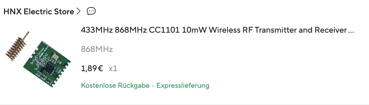
The main HW are those above you can see the costs are neglectable, for very beginners, I recommend to buy 2 from each later on soldering can be important.
Cables: all possibilities (male/female etc…) cost was around 2 EUR
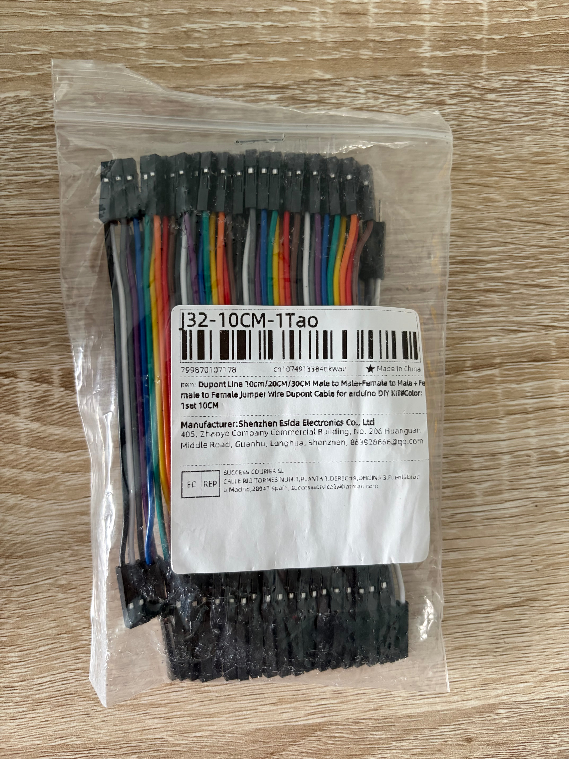
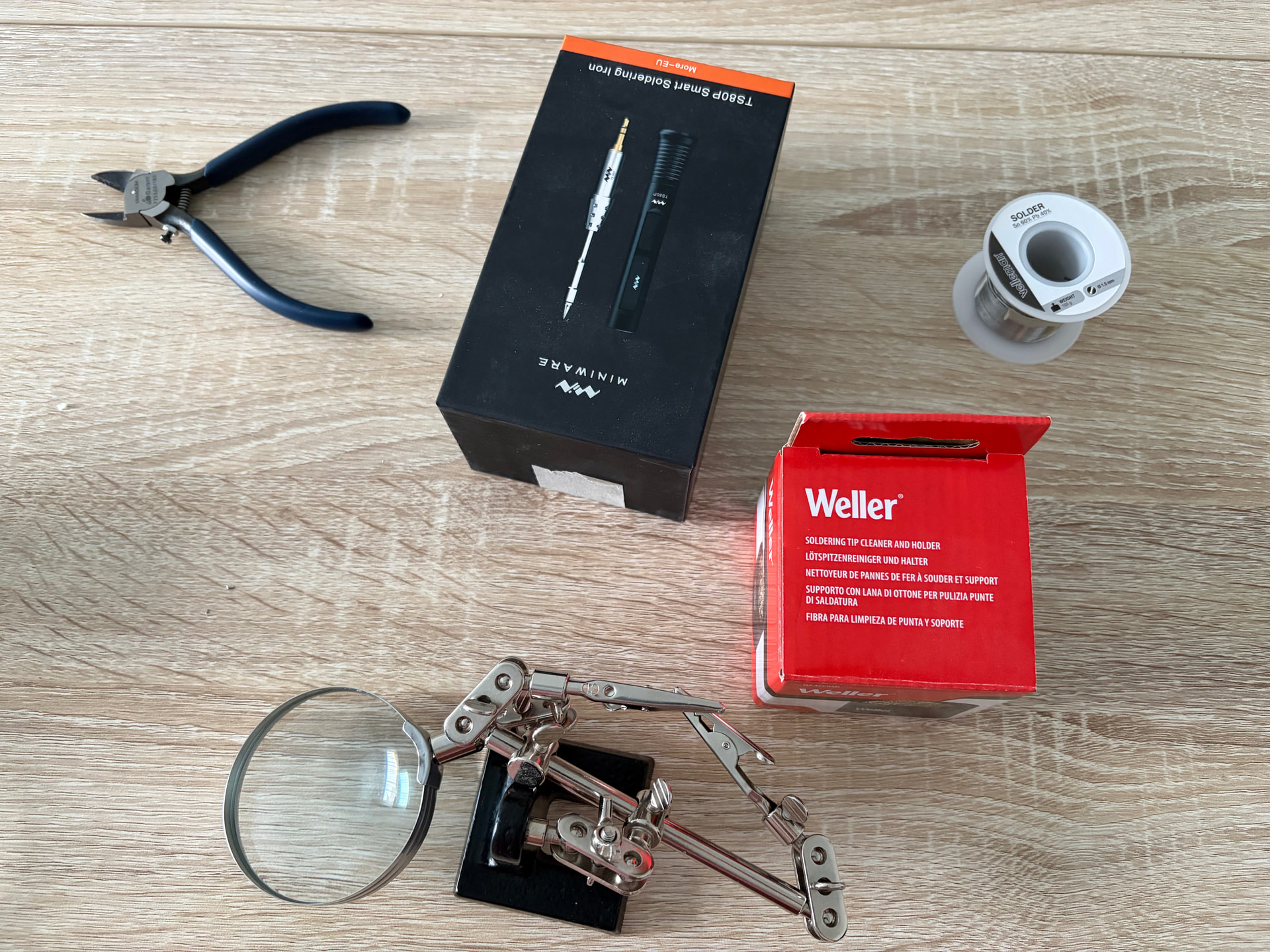
Additional HW if you have nothing in hand:
Soldering I choose TS80P from miniware, very good and solid soldering with good tip, for me it was perfect
Solder: based on tips from friends for this I choose Sn60Pb40 solder.
Clips with fixture (this is higly recommended, you will need both hands free, so something needs to hold the pins together ), soldering tip cleaner, some rubber mat, and last but not least something to drink to smoothen handshakes 
Starting with research:
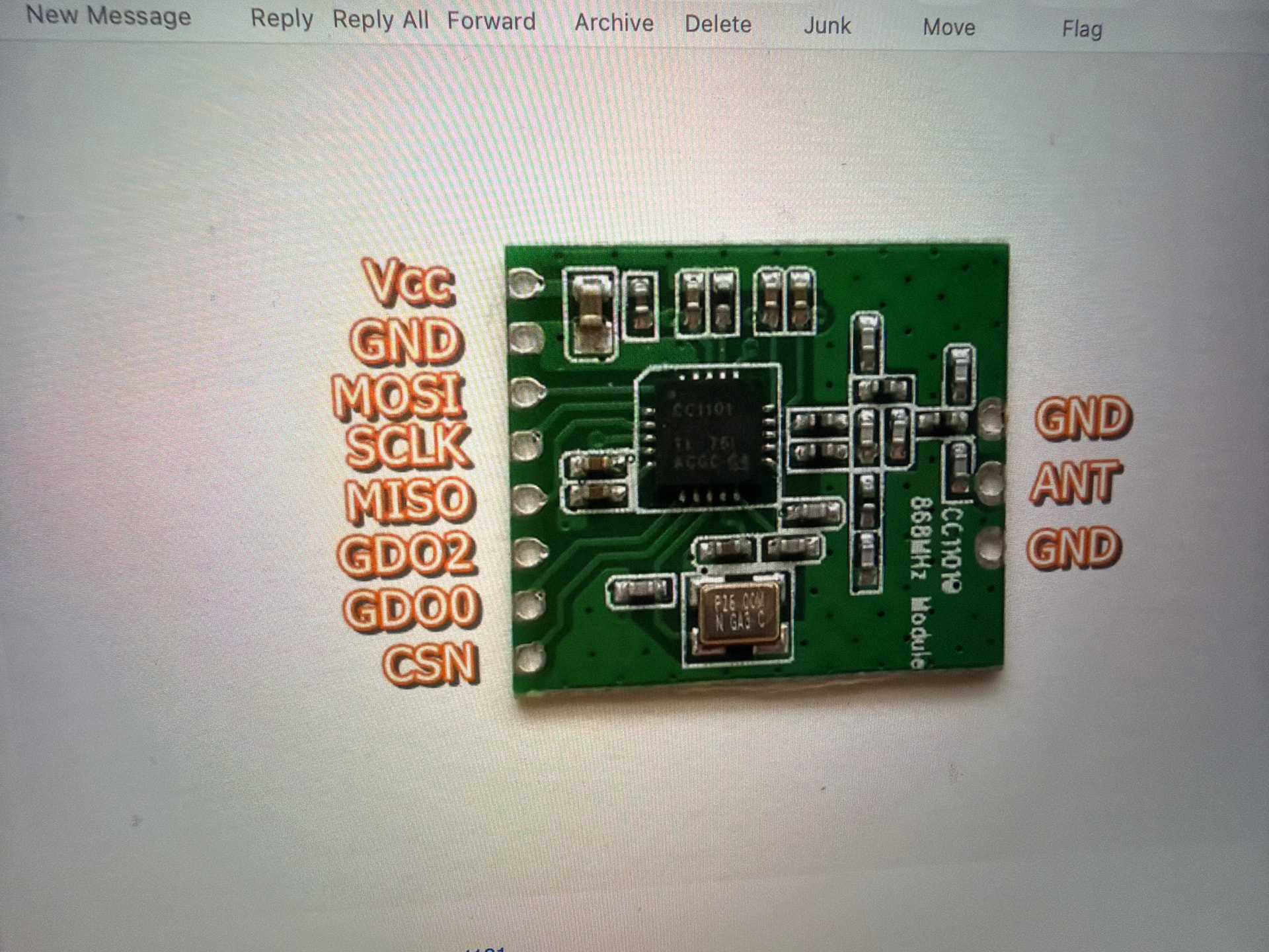
Non of the PCBs arrived with a layout what the pins do and what to connect where. For that I used google checked multiple sources, asked AI etc… Despite the fact of several sources, I was still able to screw up ESP32 and wired GPIO5 with CSN and it turned out that GPIO5 is a strapping pin. This was known to me when the whole HW was ready, I started flashing and the error message popped up in HA / ESPhome stating, you can keep GPIO5 but be aware that it is a strapping pin… So I decided to desolder it and move it to somewhere else.
Here you will see the CC1101 pins:
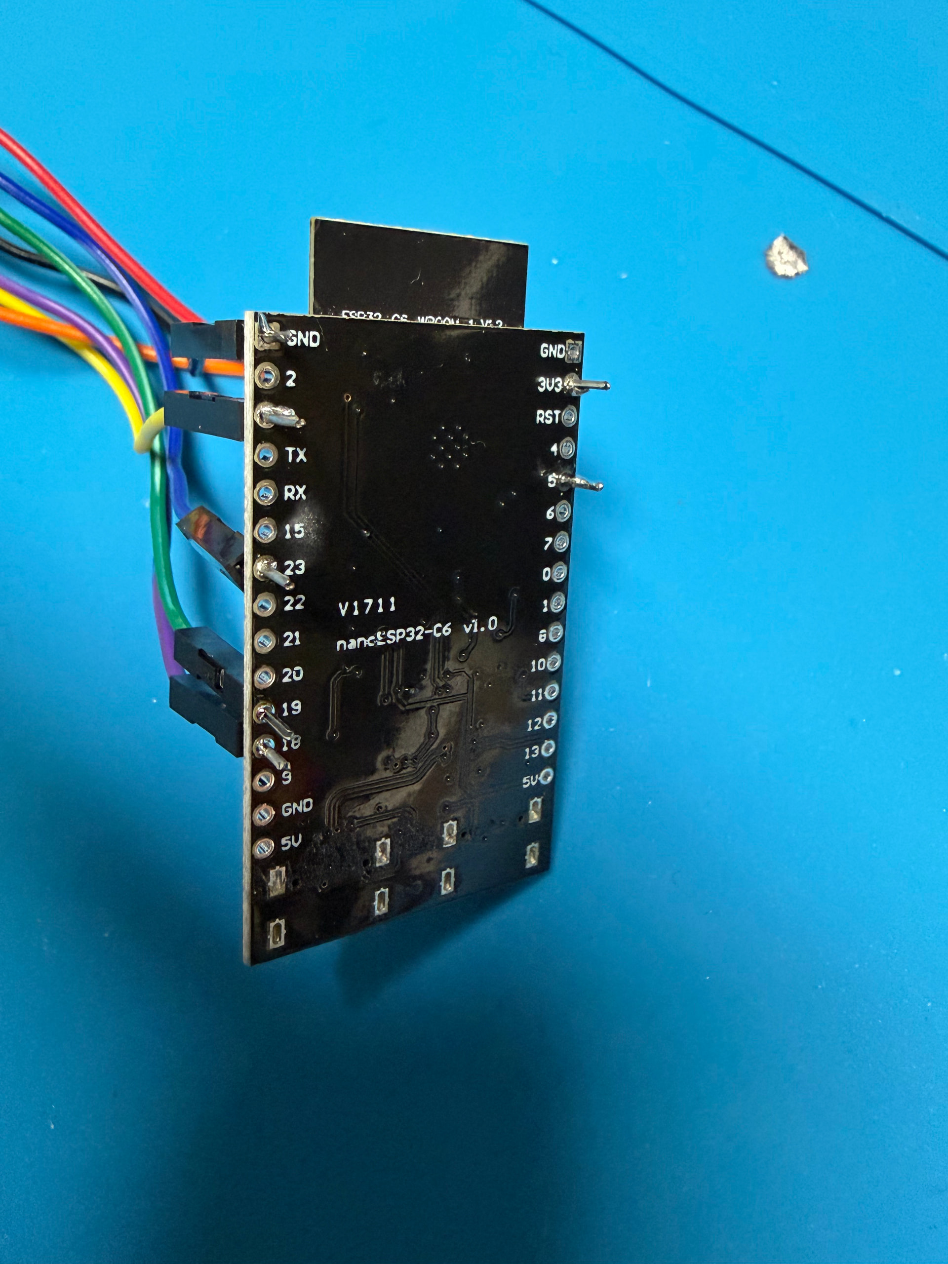
Here you will see the ESP32 pins for this project:
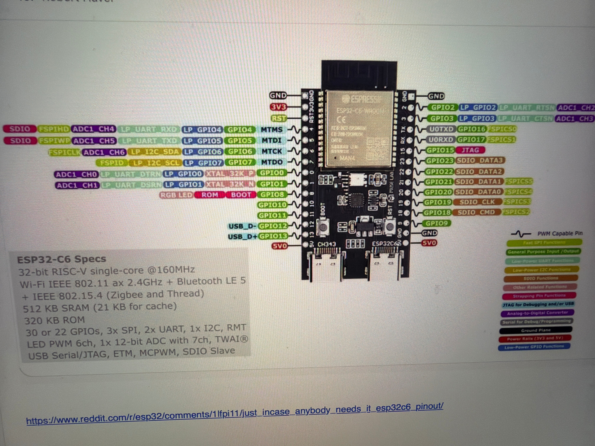
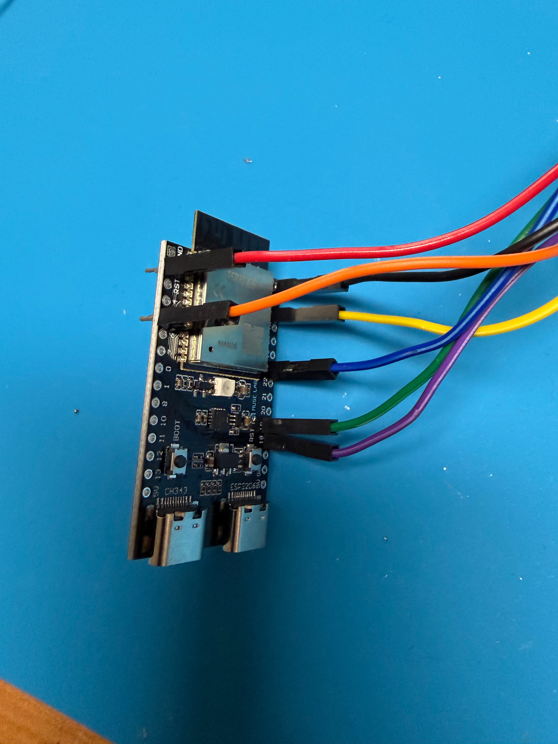
Ground, 3V was easy the rest I checked how the others did it and if I had the number in GPIO I used that, if not I used something else. Once you know what to connect where it is better to create a small table and if you have multi color cables it will help you to easily do the connections.
3,3V - VCC - red
Gnd - gnd - black
GPIO23 - MOSI - blue
GPIO18 - SCLK - purple
GPIO19 - MISO - green
nothing - GDO2 - not connected
GPIO3 - GDO0 - yellow
GPIO5 - CSN – orange (later changed to GPIO6)
Soldering the HW:

On soldering (as I am not an expert) I checked some videos, my way was: 300 degree Celsius as base temperature. First I put the solder iron close to the pin/PCB of my selection, then hold the solder just a little there, move the solder back, move the soldering iron back and that’s it. Little is OK (edit: it is really! if you swim in solder paste other pins might be connected as well and that's something you do not want) it is not welding
 You will see from my pictures that the CC1101 cannot really fit the big plastic pins and that’s why it looks so strange.
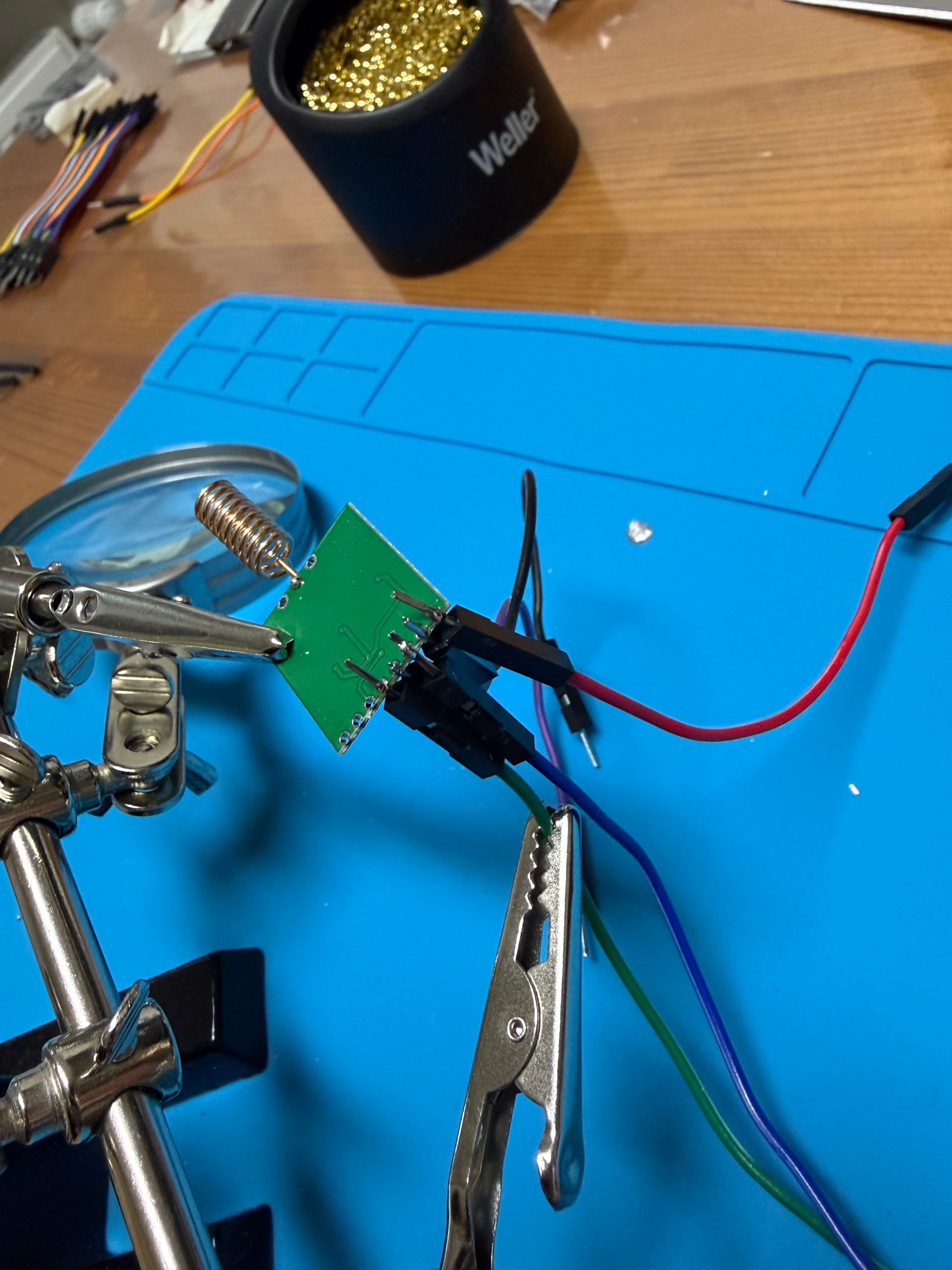
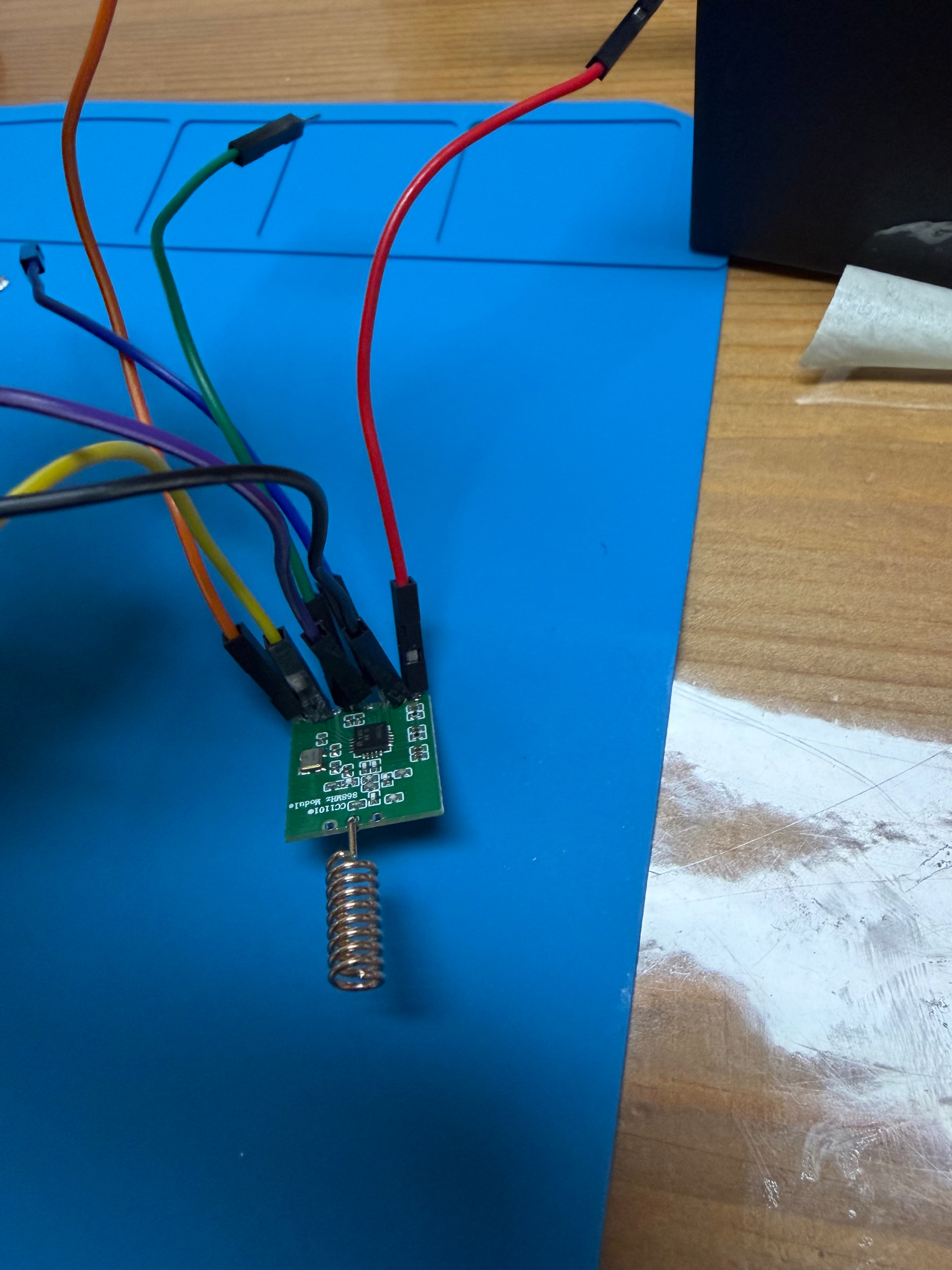

I started with CC1101, and later figured out how I am going to finish the end product (to create a cover/box/home for it, etc…) so then I soldered the ESP32 already twisting the cables in the right direction.
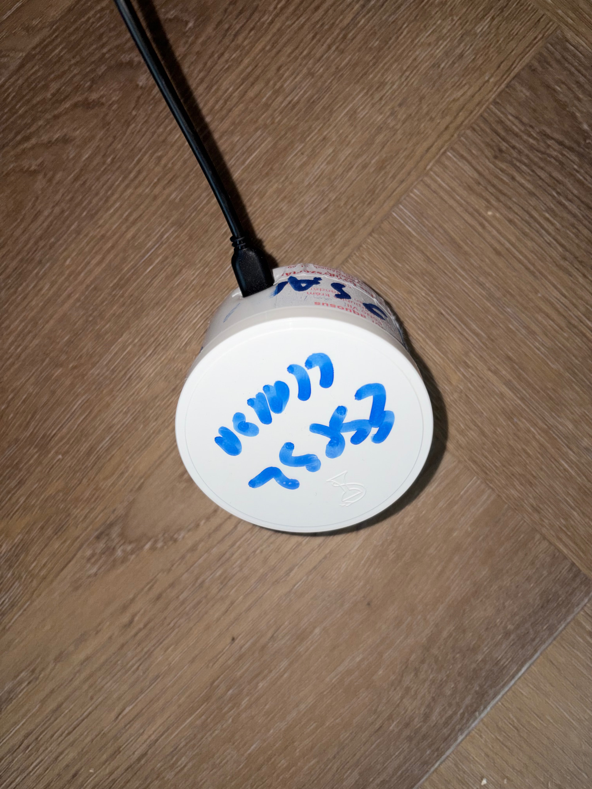
Final product in the final box:
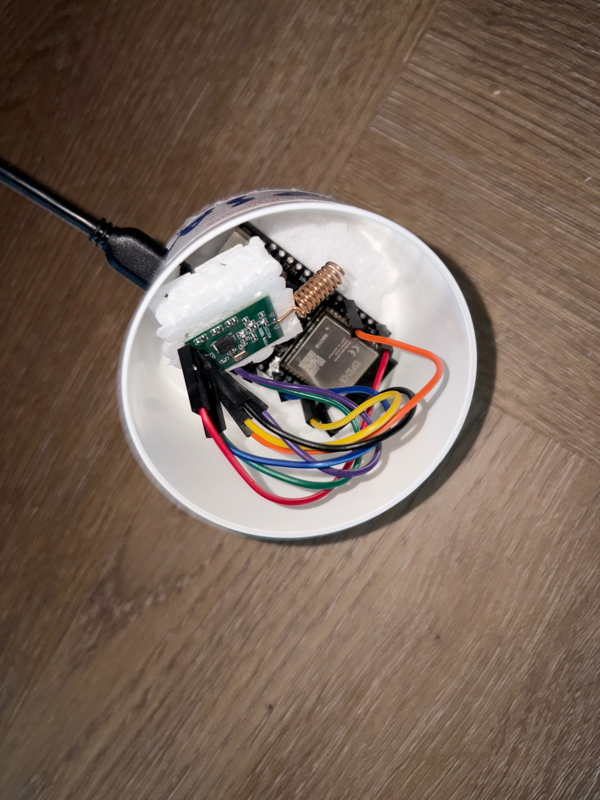
HW ready, now SW:
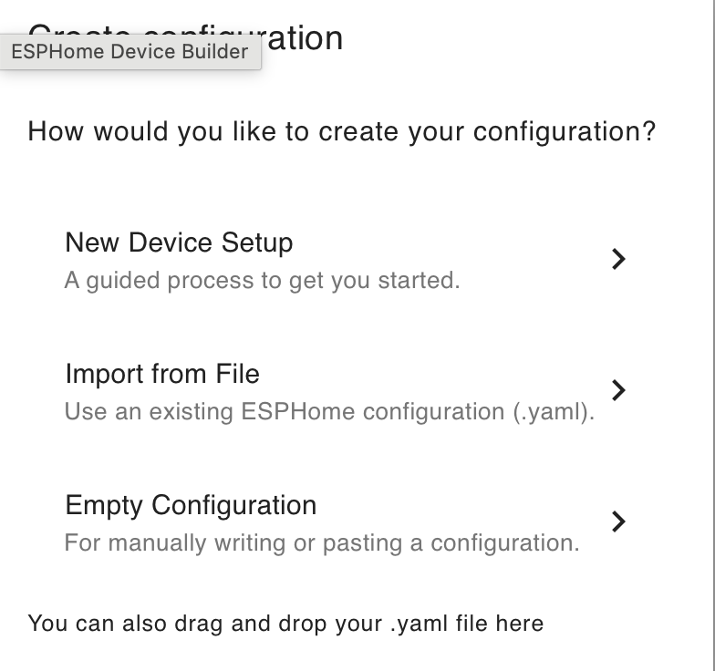
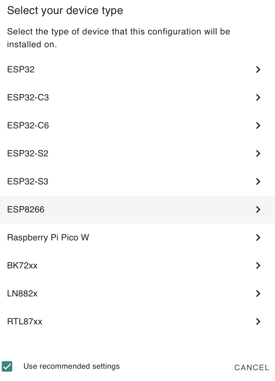
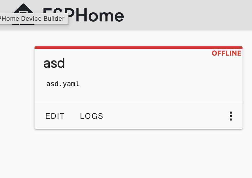
Once the HW is ready you can proceed and install ESPHome in HA. Click on the new device + green button and follow simply the on screen questions. You will need as HA informs you an USB cable which is capable to transfer data (not just power). If unsure, take your phone plug it into the computer and if the OS recognize it for data transfer, your cable will be good. If phone only the battery is loads, that’s just power, so cable is not good! I connected my ESP32 directly to the HA which is running on Pi, so I choose on the first screen "USB to the server". Then New Device setup -> give a name -> select the ESP HW my one was C6 and ESPHome already creates the tile for you. Last step is Skip based on videos in youtube


Some hints:
WIFI: this will be handled in a different file top right corner secrets. There you need to enter your SSID and password. I used my 5Ghz wifi, that was another error :-DDD, later during comply the ESP32 warned me that 5ghz wifi not working. Only use 2.4ghz !
YAML: every space matters, every white space needs to be in the right place, during comply I got several code errors etc... so after reading some pros and cons about yaml I learned that yes, really every space matters
Once it is available, click on EDIT then you can edit the YAML file directly. Here is where you need to provide the basic data.
In general the code (given by ESPhome) should be good for you as a basic
esphome:
  name: elero-ablak
  friendly_name: elero

esp32:
  board: esp32-c6-devkitc-1
  framework:
    type: esp-idf

# Enable loggings
logger:

# Enable Home Assistant API
api:
  encryption:
    key: "SOMETHING/LONG KEY="

ota:
  - platform: esphome
    password: "SOME PASSWORD"

wifi:
  ssid: !secret wifi_ssid
  password: !secret wifi_password

  # Enable fallback hotspot (captive portal) in case wifi connection fails
  ap:
    ssid: "Elero-Ablak Fallback Hotspot"
    password: "ANOTHER PASSWORD"

captive_portal:

external_components:
- source: github://andyboeh/esphome-elero
… you can also load the components from your HA directly as this project is not going to be updated anymore according to my knowledge. If you would like to do that, you need to save the files from github and upload to HA, then you need to change this section to load the code from your local HA instead of online
The port/pin setup comes next like this. You need to change according to your pin soldering, freq0-2 I left untouch.
spi:
clk_pin: GPIO18
mosi_pin: GPIO23
miso_pin: GPIO19

elero:
cs_pin: GPIO6
gdo0_pin: GPIO3
freq0: 0xc0
freq1: 0x71
freq2: 0x21
…and you need some basic shutter setup, otherwise you get an error again. Do not worry on the stuff below, just copy/paste because later you will edit this, but you need something to run the install and get into the LOG screen:
cover:
- platform: elero
blind_address: 0xa831e5
channel: 4
remote_address: 0xf0d008
name: Bedroom
#open_duration: 25s
#close_duration: 22s
#poll_interval: 5min
supports_tilt: False
payload_1: 0x00
payload_2: 0x04
pck_inf1: 0x6a
pck_inf2: 0x00
hop: 0x0a
command_check: 0x00
command_stop: 0x10
command_up: 0x20
command_down: 0x40
command_tilt: 0x24
When you ready with the yaml editing, click save and then click install. The first install will take time, at least for me it was enough time to make a tea. In several cases I was in doubt if the screen was frozen, etc… so if all done right, it is not frozen it is working, but slow as a snail. Similar experience I have each time ESP home gets an update and I need to update my code. If you click away from ESP Home during this time, and you go back to the main screen, you will see that your current application is under Installing. When that is switched to ONLINE, that’s when you are ready. It can be that several restarts will happen etc… especially the first time! When it is finished and if the wifi configured good, you can remove the USB from the pi (if you did it via PI) and actually place the device where you want (wifi needs to reach it!) and just plug it in via USB-C. The ESP32 will boot up and it will be visible in the ESPhome. Future log checking, yaml editing, can be oda OTA!
SW done, device online, ready to capture 868Mhz and check log:
Once the device is online, you can go into the LOG and use the TempoTel 2 remote to go to your cover which you would like to copy. In my case it was a bedroom cover. When you push the up button 2-3-4 times on your TempoTel 2 the LOG will capture your command and shows it to you in a form like this (Hint: when you actually press the button in the log there will be 3-4-5 entries all looks almost identical, but not really. I only copied the one which is was the real line for me. Mentioned also in the github description check only with len=29):
Opening:
[21:17:01.542][D][elero:451]: rcv'd: len=29, cnt=255, typ=0x6a, typ2=0x00, hop=0x2a, syst=0x01, chl=21, src=0x775a89, bwd=0x402df5, fwd=0x402df4, #dst=01, dst=0x402df4, rssi=-73.0, lqi=47, crc= 1, payload=[0x00 0x04 0x00 0x00 0x20 0x00 0x00 0x00 0x00 0xc0]
Stop
[21:11:11.462][D][elero:451]: rcv'd: len=29, cnt=249, typ=0x6a, typ2=0x00, hop=0x2a, syst=0x01, chl=21, src=0x775a89, bwd=0x402df5, fwd=0x402df4, #dst=01, dst=0x402df4, rssi=-74.0, lqi=48, crc= 1, payload=[0x00 0x04 0x00 0x00 0x10 0x00 0x00 0x00 0x00 0xc0]
As mentioned in the github description now we need to find the right commands and fill it back to the yaml in the ESP Home (I use bold section to highlight items from the LOG to the CODE). Most of the things as mentioned in the github it is default and for me it was the same:
cover:
- platform: elero
blind_address: 0x402df4
channel: 21
remote_address: 0x775a89
name: Bedroom
#open_duration: 25s
#close_duration: 22s
#poll_interval: 5min
supports_tilt: False
payload_1: 0x00
payload_2: 0x04
pck_inf1: 0x6a
pck_inf2: 0x00
hop: 0x0a
command_check: 0x00
command_stop: 0x10
command_up: 0x20
command_down: 0x40
command_tilt: 0x24
Down button I missed from this guide and I have not changed check and tilt, but it is the same. Many things won’t change during your setup and it will be constant like: remote_address and you found on the first cover then all of your commands, stop, check, up, down for me all remained the same.
What is changing if you start adding more covers with this method is:
-
- Blind_address
-
- Channel
Adding further covers to the yaml:
Adding more shutters, just repeate the full code CTRL+C and CTRL+V wihtout the cover: part.
During my further cover setup, I made several space errors, so all of my complys failed. Take extra care that you only paste if you have any additional space here / there
Every time you edit the yaml file in the ESPhome, always save and install.
Adding the ESPHome to HA:
If the yaml is ready and all SW is done, ESPHome running well, you can add your new ESPhome as a device so that the buttons are available on your dashboard as well. If you have HomeKit Bridge to Apple Home you can also push the covers to Apple Home and from there you can control them with Siri.
Adjusting the yaml to your needs:
What I did as a start, I commented out the traveling time and poll with #. This automatically in HA creates for your cover a simple UP DOWN STOP button. As soon as I was ready with all of my covers, I took a stopwatch and measured the travel time then I added back to the yaml all and once you have traveltime / duration included in your code, HA will offer you the slider. So you can slide for example 58% open and it will open kind of half way.
What happens if multiple HW are in use:
I need to say, because I have TempoTel 2 which controls all my covers + I have wall switches (also elero MonoSon W-868) + HA. The % and slider opening are not really working. Sometimes the family uses the TempoTel, sometimes wall switch, sometimes HA it is not accurate. But for me that’s a tradeoff what I accept. If I want accurate opening/ closing I take the cover first full open or close then the % opening works from HA.
Issues with % opening:
I also need to say when I say works, that mean I am able to use it, but for example 25% opening for me "as a simple user" I would expect ¼ of the cover is open. Now in reality it is not open at all, only the little ventilation wholes are visible That’s my 25 % . 50% however works well, then the shutter stops almost always in middle. I am currently working on this to fix it somehow, so if anybody has more experience here, please chime in!
I hope you enjoyed my guide. I was a bit worried when I started this, but all in all it was easy, even soldering is not a big deal if the right equipment is on hand. I thank you for all of those who opened / commented on previous posts, github, etc on this topic because there is sooooo little about Elero mentioned, however bringing 868Mhz covers into HA with this method is not a big deal at all.
If some experts reading this, please feel free to comment any segment, so that if non experts would like to do the work they understand better what and how to do. My challenge was in many cases or descriptions in github or videos over youtube, that by time it outdates, or misses "basic" informations, because it is expected to be known. I hope this guide will bridge those gaps and non-experts will also find it easy to build and use elero shutters with HA as I do now