I’m strugging getting data returned from my Eastron SDM630 Modbus in combination with a Waveshare RS485 to ETH (B) device. I have read all the posts above and tried many of the examples but still no result.
The error message I consistently get for all entities is:
Eastron Modbus: Error: device: 103 address: 72 -> Modbus Error: [Input/Output] ERROR: No response received after 3 retries
It seems my Waveshare device is operating as it should since I see the correct lights (Link light = blue, Active light = blue so it should be returning data). I’m using baudrate 9.6k, parity none, stop bits 1 on both the Waveshare and SDM630. I have triple checked my modbus addresses (101 and 103; in addition I have also connected a Nibe heat pump which uses address 1 and no problem in receiving data from this device).
What else have I tried in various combinations (without result):
Baudrate 38400
Protocol Modbus TCP to RTU
type ‘rtuovertcp’ as well as ‘tcp’
I notice in previous posts the use of ‘count: 2’ and ‘float32’ to specify sensors. However, I’m getting an error message when I use this (float32 already specifies 2 registers to read)
@fsfikke@jghek can you perhaps have a look at my problem … thanks in advance.
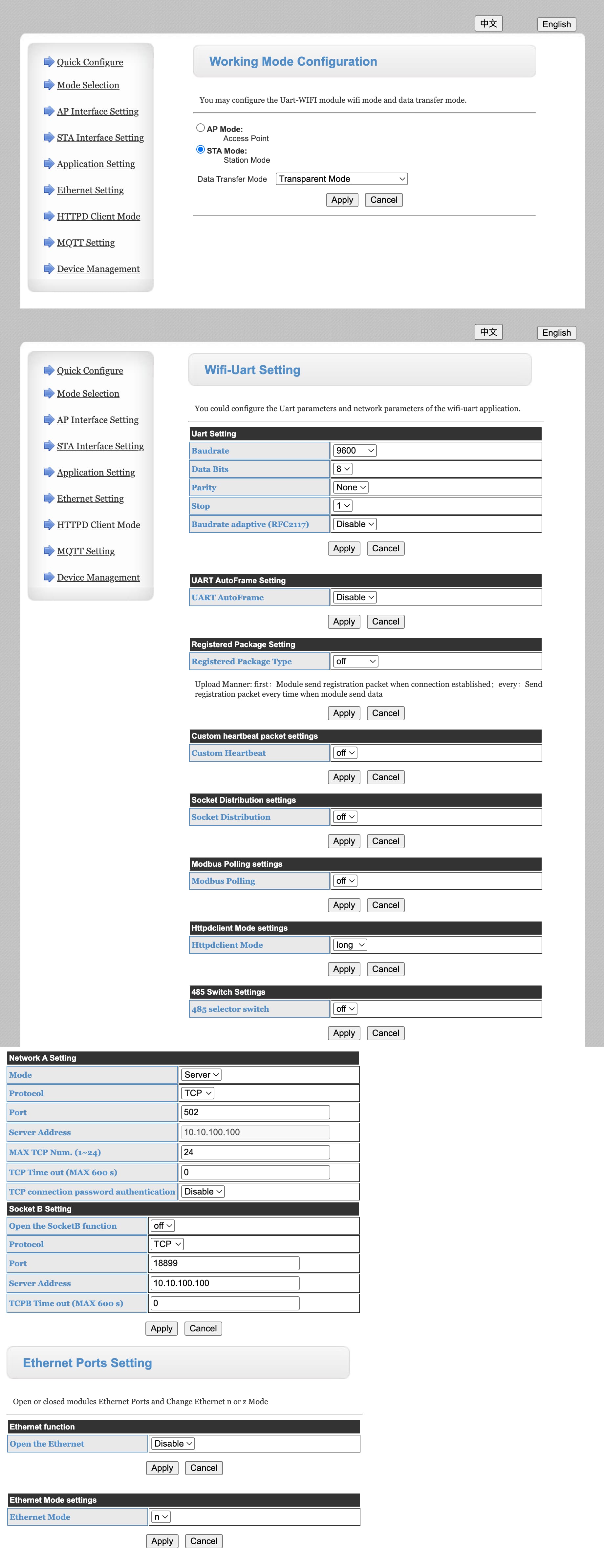
I have reset my RS485-to-ETH to factory defaults and changed the IP adress to DHCP (static 192.168.200.78), port 502, work mode ‘TCP Server’ (default), 9600 baud.
I can access the converter with Modbus Master app. However, I consistently get an Error code 2 (‘Illegal address’). See attached screenshot (modbus instruction and resulting error code visible at bottom of screenshot).
I also tried different baudrates but this didn’t make any difference.
I also tried start address 1 but this also didn’t make a difference. I attached an over view of the first few SDM630 input registers below. I still think the addresses should be even and starting from 0, 2, 4 etc.
What I did discover just now is that even with the SDM630 not connected to the RS485-to-ETH converter, the error message is still the same “Illegal address”. That strikes me as odd.
I used another modbus analyzer (QdModMaster instead of Modbus Master). QdModMaster gives more and better detail wrt response codes:
when querying the ‘modbus diagnostics’ QdModMaster clearly distinguishes between the SDM630 being connected to the gateway (response ‘Read diagnostics data failed. Error : Timeout’) or not (response ‘not connected’). My conclusion is that my SDM630 is connected.
When trying to read an address the response is consistently ‘Read data failed. Error : Timeout’
QUESTION: One earlier remark above was to swap the A and B labelled connectors (+ and -). Can I try this without damaging the gateway or SDM630?
I have 4 eastron SDM 72DM also with modbus which I have to connect to my HA Server running on a Pi 4 roughly 35m aways (cable meter).
Any recommendations what to look for and what would be usefull ?
ESP Data Collector or is there a hub that could collect the data of these 4 and send those via LAN ?
LAN and WLAN are available - otherwise I would have to lay a new 35 m long LAN cable to use its 4x twisted pair cables for the 4 eastron SDM72 meter.
yes, you can switch them around. But usually there is clear description from the meter and which pin to be use on the adapter or maybe inverter.
Might be good to show your current wiring too. Cause it is quite unusual in my opinion.
If you have the right wires connected properly then the FIRST SIGN should be that you should see a TELEPHON RECEIVER in the upper left corner, you know back from the 80s
This is a photo which I had put together to make it clear.
Right wires (usually people tend to use a LAN Cable with 4 twisted pair wires) and properly connected is key.
If you are starting always try to start with a short pair of cables first cause that makes things a lot easier.
I did it with an old LAN cable where I had cut off the RJ 45 plugs on one site and used the other RJ45 on the inverter side.
WHen that had worked for me I added a double clutch to the cable as connector cause I added a 35 m long lang cable which made a total length of 37 m. I took the LAN and went throught the rooms of the house to the inverter room to do the next checke if the SDM could communicate again this time with the inverter. Once it had worked out I started to finaly pull the wire via attic and roof as the final solution.
Hi guys,
I have this meter connected to HA and hardware/ software wise everything is working. The thing I cannot figure out is how to setup the energy meter in terms actual data… I have the meter connected at the entry of my 3 phase installation. The energy can flow in and out. My question is:
Which registers exactly, and how recalculated, can be used to get the actual balance of energy (in kWh) that is present at the moment? I mean here, there must be a better way than integrating the power on each phase and summing it? The thing I dont get about this meter is why is it summuing the import anx export kWh values instead of subtracting one from another.
Also, how to hook it up with the Energy panel in home assistant?
From the Eastron Documentation, PDF Here. I also used software like Modbus Master to fiddle around and try stuff. In some case there is an offset of 1, so it’s helpful to try first.
I’ve read you project description. Here’s my approach, but others would also be valid. It all comes down to trade-offs. Here are some of my rules for hassle-free/wife-happy tinkering:
Standard over Custom. If there is a of-the-shelf product that exactly does what you need (and it is affordable), go for it. They will typically have better casing, run longer, require less maintenance and doesn’t break right before you want to go on holiday (and if it does, you order a new one).
Wired connections over WiFi. WiFi is cool, but by nature not as reliable as wired connections. Also, you do not want integral part of your house tied to your WiFi SSID named to your cat, since it would be hard to sell your house like that. If you are running wires outdoor, shielding is needed (physically and magnetically).
Less is more. Using a lot of hardware is cool, but eventually stuff breaks. Tinkering is fun, but forced tinkering because it stopped working (again) a lot less fun.
So, I would go with a simple RS485 network. Just two wires. If you have 4 (slave) devices, you can wire them in parallel. Polarity matters! A needs to go to A everywhere. In terms of RS485, 35m is nothing. You can easily run up to 10M here, but since the Eastron only goes up to 38400 baud (bps), a 1000m would also be possible. I think at this speed and length (< 50m) you do not even need a termination resistor. Termination resistor prevent signal reflections. In the rare case that you have issues, connect a termination resistor of 120 ohm at each end between A and B. For conversion I would go for the Elfin-EE11 or the WaveShare RS485 TO POE ETH (B). That will act as a TCP MODBUS server to access all slave devices. For wiring you can use network cable, or even twisted phone wire. It is way easier to work with and RS-485 doesn’t need CAT7. If you are running outdoors and you want to be really protective, you could keep the MODBUS server close to the devices and run your network over fiber outdoors. A Mikrotik RB260GS is a great tool here.
Thank you for helping the others. I use this SDM630 also with my Victron system.
By default, Modbus runs at 9600 baud, which is too slow (with Victron and home assistant). Victron continues polls the SDM630 for the actual data. But it also doesn’t hurt to increase the baudrate for home assistant. Increase it to 38400 baud for better performance.
You say you use 8888 as local port, I use 502 (which I changed in your config)
But don’t think that will be the issue right?
Do you have any clue please?
If someone is trying to get SDM630 working with Waveshare rs485 to wifi/eth module (https://www.waveshare.com/rs485-to-wifi-eth.htm), then here is the cfg which worked for me (I use WiFi, not RJ45):
Spent quite a lot time to get it working, but looks like the problem was wire connection… at some point when measuring voltage in wires and attaching oscilloscope just noticed that not only tx is blinking but also rx light started to blink on waveshare device…