I’d like to share a project for integrating the Engelmann Sensostar heat meter with Home Assistant using ESPHome. I’ve always wanted to read my heat meter’s data in Home Assistant, and since I already owned a Sensostar, I started looking for a solution. I found an existing project on GitHub from Brambo123 but couldn’t get the necessary hardware. So, I decided to use it as a base and develop my own solution.
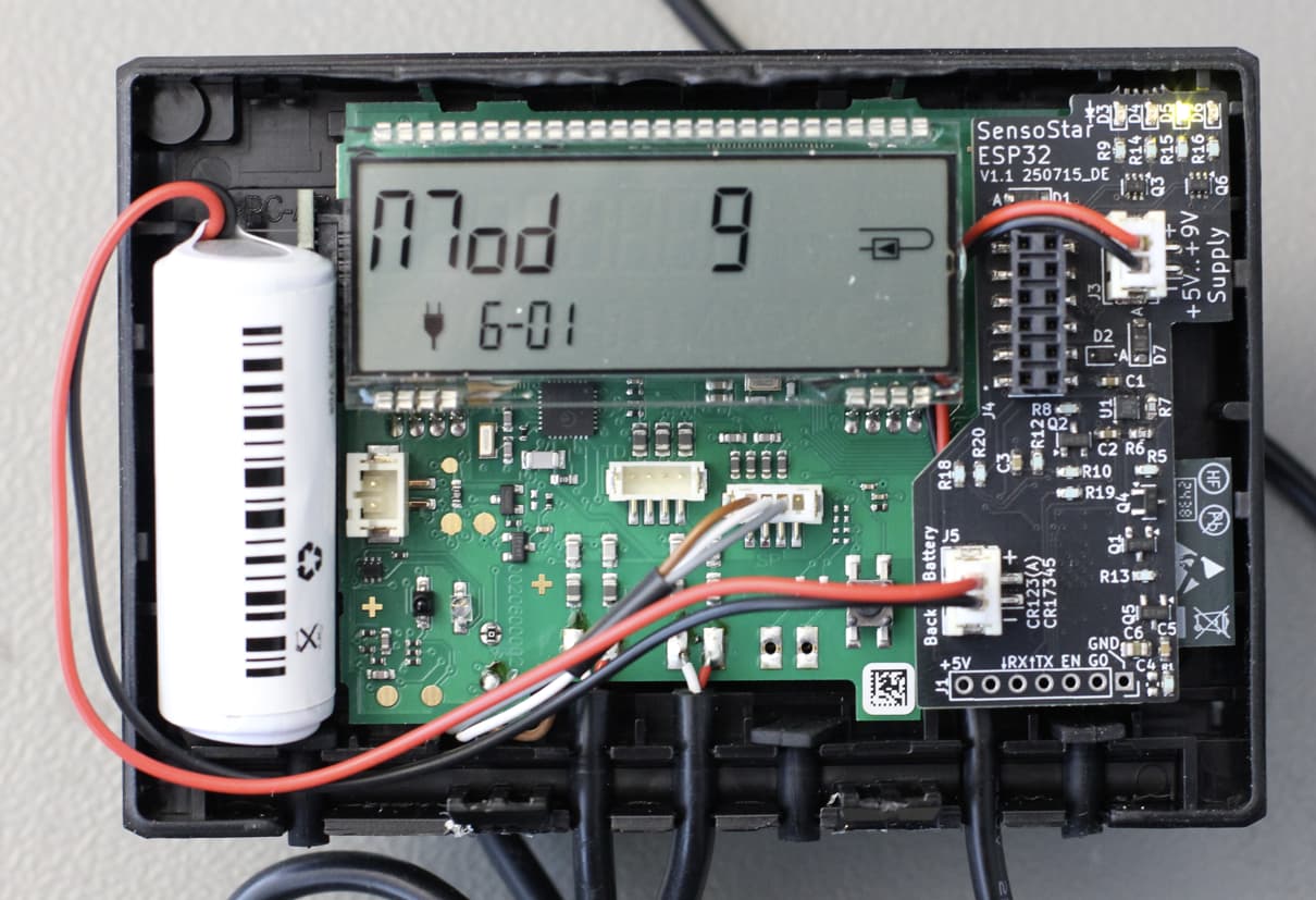
I designed a custom PCB that fits directly onto the expansion headers of the Sensostar-U and Sensostar-E models. It will likely work with other models too, but these are the only ones I’ve tested so far.
The board is equipped with an ESP32 and includes some cool features:
It can read data from the heat meter.
It monitors the backup battery.
It automatically disconnects the ESP32 when the external power supply is gone to save the backup battery.
Four status LEDs show you what’s happening:
Heartbeat
Reading data from the Sensostar
Flash programming in progress
Wi-Fi status (blinks when disconnected, solid when connected)
The board is automatically discovered by Home Assistant.
To allow for more frequent data readings, I also designed a small PCB that signals the Sensostar that an external power supply is present.
I’m now looking to industrialize this product and start a small production run. The goal is to offer you a ready-made, plug-and-play solution so you don’t have to solder anything yourself.
I’m trying to gauge interest, and if about 50 people want to buy the finished product, I will move forward with a small manufacturing batch.
Interested?
If you’re interested in getting the finished hardware with pre-installed firmware, just send me an email at: esphome_sensostar"at"avboard"dot"de
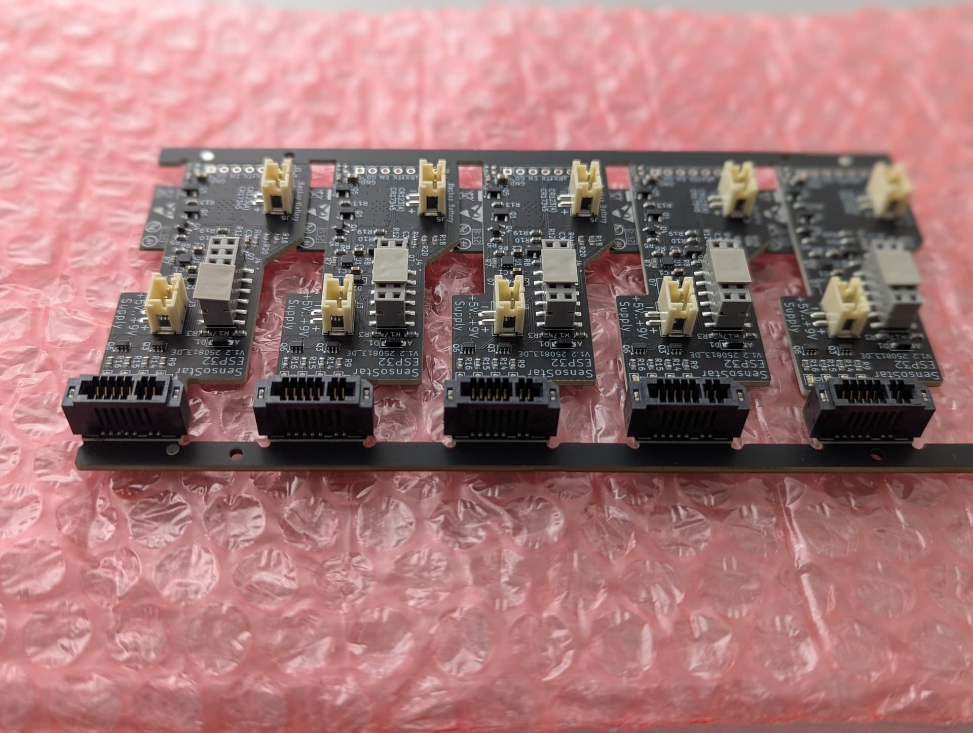
Just a quick update: I tested version 1.2 and everything worked well.
The increased current drain that I observed in version 1.1 when disconnecting the power supply has now been fixed.
Backup battery consumption is now as follows:
Ibat when +5V connected: 1.1uA
Ibat when +5V unconnected: 2.7uA
Ibat when +5V unconnected and powersupply indication set: 59uA
There are also Sensostar E and U models on the market that come with an RF module pre-equipped. These are NOT compatible because the expansion connector is not present.
Always check that the ‘Modulschacht’ is present. This is usually the case when the optional M-Bus module from Engelmann can be purchased for it.
I’m also working on an updated PCB version.
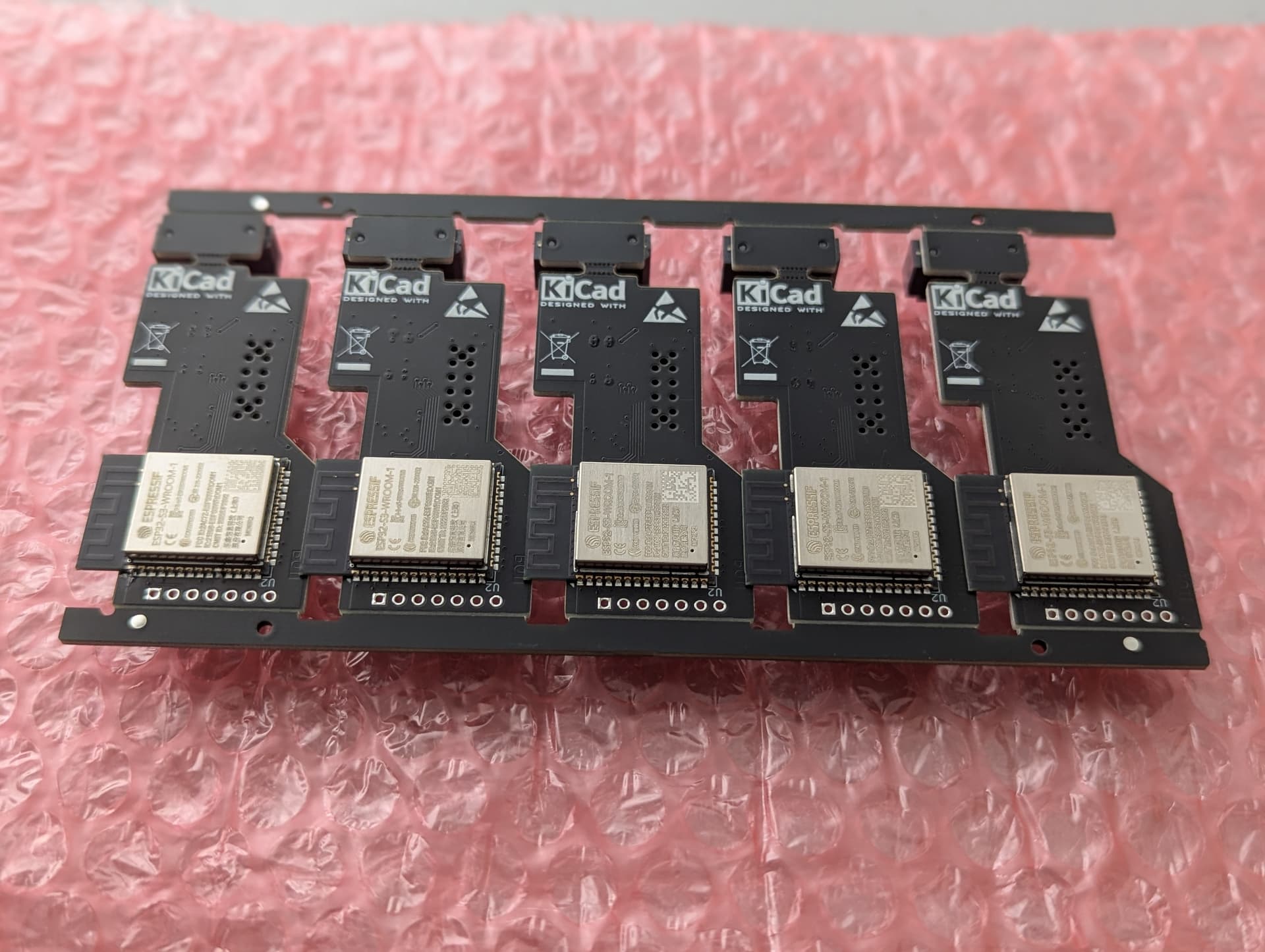
I noticed one thing about your version: the ESP is on the bottom.
Having SMD components on both sides of the PCB makes assembly quite expensive.
Yes, it’s more expensive, but I want to use the ESP32-S3-WROOM-1 module because, in my experience, it’s superior to other ESP modules in terms of transmit power and sensitivity.
In my opinion, this is the best compromise for having one component on the back. It would also be possible to switch the module to the other side, but it would most probably end up with several components on both sides.
I don’t have enough experience with the ESP-C6-MINI-1 module to comment on its RF performance.
The datasheet does state that the C6 chip has more sensitive reception than the S3, but the antenna is also important.
Don’t forget there’s also an ESP32-S3-MINI-1, and an ESP32-C6-WROOM-1.
There are just too many options
My code is primarily the esphome component.
And then some minimal example code to get it working.
If a user wants to add MQTT, they can do so themselves.
The idea of ESPhome is that you can customize your own configuration, not that you build an extensive web interface with all sorts of options.
I don’t know why you added an LED function to the sensostar component.
You can do that in the configuration:
And a big tip for your repo:
You mention that people are allowed to create issues, but issues is disabled.
Excellent solution and glad you have MQTT working nicely!
I am very looking forward to the boards. The heating period has begun and I’d love monitoring my heatpump and heat consumption again.
PCB population is done I guess: Any idea when the 1st boards will be sent out?
One additional Question: Did you know, when the 2nd bord will be sent out? I’m in the same situation like Jan, heating period was started an in the moment I notice every evening the power-value and put it manually to the home-automation.
I’ll receive the fist boards this week.
But as you might now, I’m spending my free time in preparing the shipment what in detail means:
Crimping the USB & Battery cable
Spot weld the battery connection
Flashing the SW
Do a functional test
Unfortunately the connector for the PCB-Edge of the Engelmann PCB is the wrong one and the fixing pins on both sides must be manually removed with a Dremel.
I think I can ship 5…10 boards/week what means the whole process will take more than a month.
Could you please explain what the request_messages of init_states 0 / 1 / 2 and 4 do?
init_state 3 and 0xFF are almost clear.
I’m currently looking for a way to set/correct the internal clock of the counter, possibly regularly via NTP. Maybe you have the necessary information,
By the way: great work from both of you (Bram / Dirk)!!
On my fork of your repo I’m using the “ESP32-C3 Super Mini” and actually I’m testing for the “Xaio ESP32S3” which has a little more power.
To be honest, I have no idea about most of the initial data.
I simply created a traffic dump from an original Modbus module.
It works, so I don’t feel like figuring out what is actually being sent.
I only modified the part that sets the text on the screen.
That’s why it displays “ESP32” on the meter
By the way: I updated the initialization timing.
It was simply sending the next section every 500ms.
Now it waits for a response and then sends the next section.
I also discovered that the current software’s calculated power isn’t entirely accurate.
Apparently, the meter correctly accounts for the fact that cold water is heavier than hot water, and therefore also the energy density.
So, some adjustments are needed to get that correct.
I added the feature because my meter doesn’t measure cooling power, but my heat pump can cool.
I have received the first ten PCBs. Aren’t they nice?
The only issue is that the PCB edge connector is the wrong one and must be modified manually. The other things look promising.
I’ll start sending emails to the first ten people who ordered tomorrow.
The rest of this batch will arrive within the next two weeks.
Hopefully the first of you will have got your hardware by now.
I’d be interested to know what condition the bubble wrap envelope was in when it arrived in your postbox.
If there are issues, I’ll switch to “Maxibrief Boxes”. I’d like to avoid that if possible, as it would increase the shipping cost.
The Sensostar ESPHome board comes with preinstalled software.
If you want to build an own version, you need to modify the 2nd and 3rd line of the yaml file.
The device name has the last 3-bytes of the MAC address as appendix. To flash the device over the air this name must match the entry in the yaml file and name_add_mac_suffix: must be set to false.
This is how it looks like in the GitHub repository
  name: sensostar
  name_add_mac_suffix: true
  comment: SensoStar Energy Meter
Assume you device name is “sensostar-a32ad0” your yaml file should look like this:
esphome:
  name: sensostar-a32ad0
  name_add_mac_suffix: false
  comment: SensoStar Energy Meter