I decided to post this final form as I feel like even though there’s a lot of information out there, for me it was very hard to find since I didn’t know what to look for (i.e. baud rate).
Oh much thanks! I was so naive to guess that the relay is controlled by low/high voltage from GPIO0/2. Then I realized it has a STC15F104-SOP8 MCU on the board.
Hello,
I tried to use the configuration in above. But it is still the relay not responding to the switch and the LED on the board continuously blinking.
Do you know what is the root cause of the issue?
Sorry for bumping, but for mine the MCU’s factory flashed code on mine seems broken and all it does is twitching the relay (and the red LED onboard) repeatedly after powering up. I did the following to have the ESP-01S control it directly, in case anyone want that:
Remove the MCU
Bridge the number 6 and 7 pin of the MCU solder pad
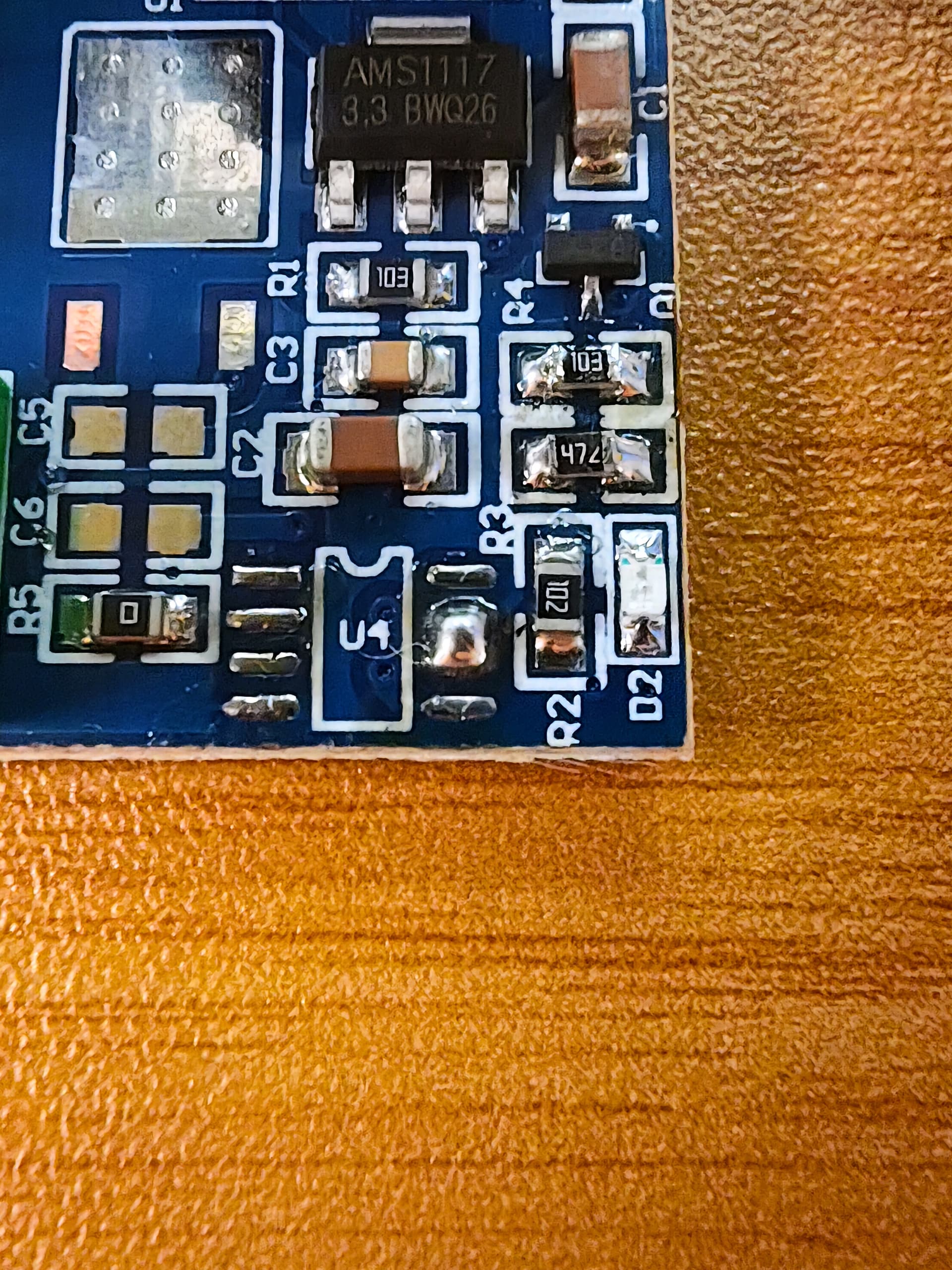
Swap R3 and R4 (the 3.3V output by ESP-01S is not enough to drive the transistor fully on with 10K in series and 4.7K to ground, but it works fine if 4.7K in series and 10K to ground instead, so swapping is the simplest solution without needing any more SMD resistors)