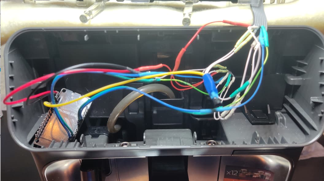
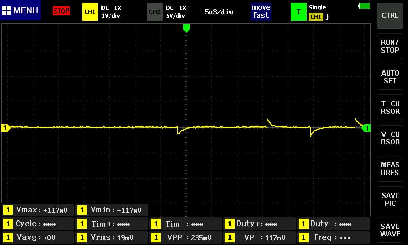
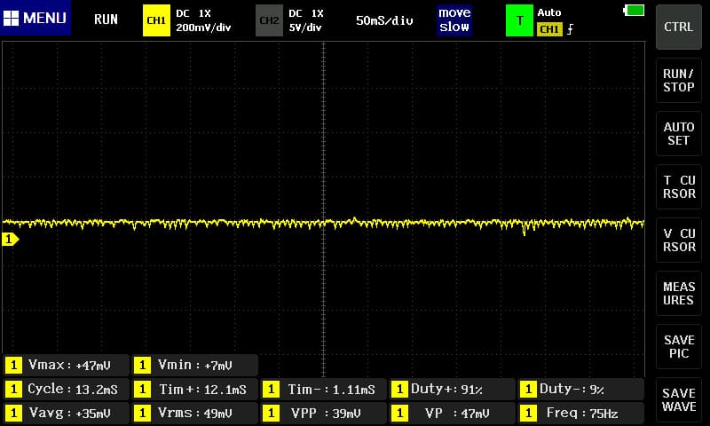
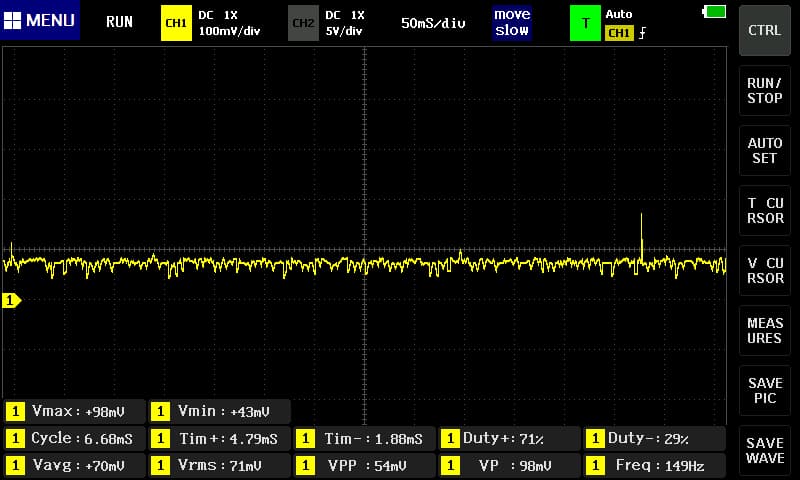
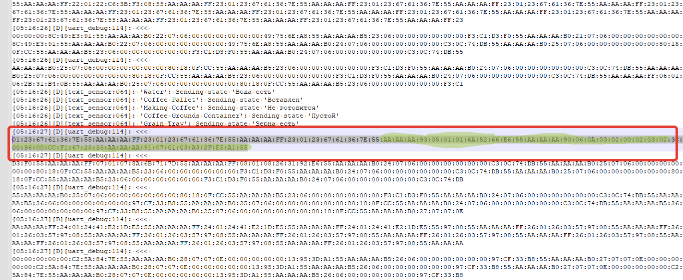
By connecting the logic analyzer in parallel according to this scheme, I was able to see the data from the screen and from the motherboard

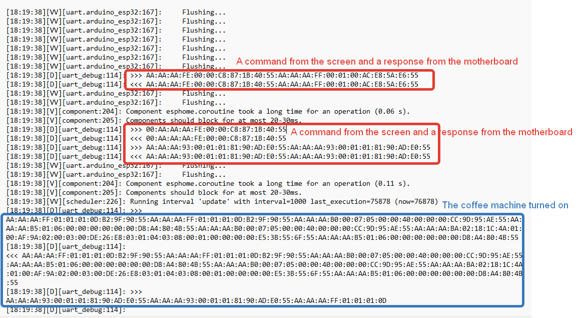
Example of turning on a coffee machine


Display, canonical.txt
Display, plain.txt
Display, with offset.txt
Motherboard, canonical.txt
Motherboard, plain.txt
Motherboard, with offset.txt
As I noticed later that when the uart_mitm component is running, the coffee machine turns off after 20-22 minutes, which forced me to abandon the uart_mitm component and given the knowledge that dummy_receiver: false should be turned off in the uart_mitm component, then I decided to try it in your component and it worked, the coffee machine now turns on and does not turn off during the entire waiting time. I specified 180 minutes. Here is my code using your component.
logger:
  level: DEBUG
  baud_rate: 0

external_components:
  - source: github://TillFleisch/ESPHome-Philips-Smart-Coffee@main


uart:
# UART connected to the display
 - id: uart_display
   rx_pin: GPIO16
   tx_pin: GPIO17
   baud_rate: 115200
   stop_bits: 1
   data_bits: 8
   parity: NONE
   rx_buffer_size: 256
   debug:
     direction: BOTH
     dummy_receiver: false

# UART connected to the mainboard
 - id: uart_mainboard
   rx_pin: GPIO3
   tx_pin: GPIO1
   baud_rate: 115200
   stop_bits: 1
   data_bits: 8
   parity: NONE
   rx_buffer_size: 256
   debug:
     direction: BOTH
     dummy_receiver: false


philips_series_2200:
  display_uart: uart_display
  mainboard_uart: uart_mainboard
  power_pin: GPIO12
  id: philip
I also learned by experience that if we cut the ESP into the coffee machine, then any deviation in these parameters leads to the fact that the coffee machine does not turn on at all, not to mention the control. These parameters are standard and are used by default in the ESPHome settings and you can omit them
   baud_rate: 115200
   stop_bits: 1
   data_bits: 8
   parity: NONE
The data indicates that the activation is answered by the command either AA AA AA FE 00 00 C8 87 1B 40, or 55 AA AA AA FF 00 01 00 AC E8 5A E6, or AA AA AA FE 00 00 C8 87 1B 40 55 AA AA AA FF 00 01 00 AC E8 5A E6, but none of the commands work. I had doubts that the ESPHome does not send a signal, but after checking with a logical analyzer (connection diagram below), the question disappeared. ESPHome sends a signal and the logical analyzer caught the bytes and the bytes were transmitted correctly. I’m missing something and I can’t figure out what, and I don’t see any other options. I really need help. Thank you.

- The coffee machine with this command
AA AA AA FE 00 00 C8 87 1B 40does not turn on
button:
  - platform: template
    name: "Button 1"
    on_press:
      - uart.write:
          id: uart_mainboard
          data: [0xAA, 0xAA, 0xAA, 0xFE, 0x00, 0x00, 0xC8, 0x87, 0x1B, 0x40, 0x55]
- The coffee machine with this command
55 AA AA AA FF 00 01 00 AC E8 5A E6does not turn on
button:
  - platform: template
    name: "Button 2"
    on_press:
      - uart.write:
          id: uart_mainboard
          data: [0xAA, 0xAA, 0xAA, 0x93, 0x00, 0x01, 0x01, 0x81, 0x90, 0xAD, 0xE0, 0x55]
- The coffee machine with this command
AA AA AA FE 00 00 C8 87 1B 40 55 AA AA AA FF 00 01 00 AC E8 5A E6does not turn on
button:
  - platform: template
    name: "Button 3"
    on_press:
      - uart.write:
          id: uart_mainboard
          data: [0xAA, 0xAA, 0xAA, 0xFE, 0x00, 0x00, 0xC8, 0x87, 0x1B, 0x40, 0x55, 0xAA, 0xAA, 0xAA, 0xFF, 0x00, 0x01, 0x00, 0xAC, 0xE8, 0x5A, 0xE6, 0x55]
I upload all the files here, schemas, logs from esphome, records from the logic analyzer, decoded files
 , which turns off the coffee machine.