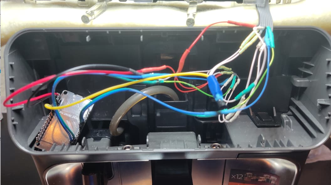
Connected the BS170 transistor. About the scheme in a little more detail will be below.
The output voltage is +5V, so it should be
I added a switch to control the transistor, which, in theory, should interrupt the power supply to the screen and feed it again. When we do this, we see from the logs that the coffee machine is trying to start, but this does not happen. The coffee machine does not turn on and the screen does not turn on either.
switch:
  - platform: gpio
    pin: GPIO14
    name: Display
    internal: False #Скрыть - true \показать - false
    id: id_switch_display
    restore_mode: ALWAYS_ON
    on_turn_off:
    - delay: 500ms
    - switch.turn_on: id_switch_display
I created a button to turn on the coffee machine, through which commands are sent every 18.536000000ms, and then a command is sent to restart the display. The coffee machine does not turn on because there is no answer about the motherboard
I made a lot of different combinations for the test. Here is an example of two commands
Option 1
  - platform: template
    name: "Turn on 1"
    on_press:
      - uart.write:
          id: uart_mainboard
          data: [0xAA, 0xAA, 0xAA, 0xFE, 0x00, 0x00, 0xC8, 0x87, 0x1B, 0x40, 0x55, 0xAA, 0xAA, 0xAA, 0xFF, 0x00, 0x01, 0x00, 0xAC, 0xE8, 0x5A, 0xE6, 0x55]
      - delay: !lambda "18.536 ms;"
      - uart.write:
          id: uart_mainboard
          data: [0xAA, 0xAA, 0xAA, 0x93, 0x00, 0x01, 0x01, 0x81, 0x90, 0xAD, 0xE0, 0x55]
      - delay: !lambda "18.536;"
      - switch.turn_off: id_switch_display
Option 2
  - platform: template
    name: "Turn on 2"
    on_press:
      - uart.write:
          id: uart_mainboard
          data: [0xAA, 0xAA, 0xAA, 0xFE, 0x00, 0x00, 0xC8, 0x87, 0x1B, 0x40, 0x55]
      - delay: !lambda "return 18.536;"
      - switch.turn_off: id_switch_display
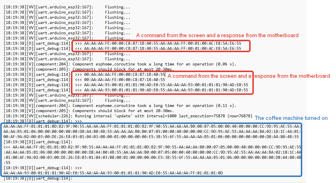
Where did I get the delay of 18.536 ms? When I was taking data through a logic analyzer and viewing data through the Pulse View program, I decided to measure the time between sending a command from the screen and receiving a response from the motherboard, and this time was 18.536000000 ms
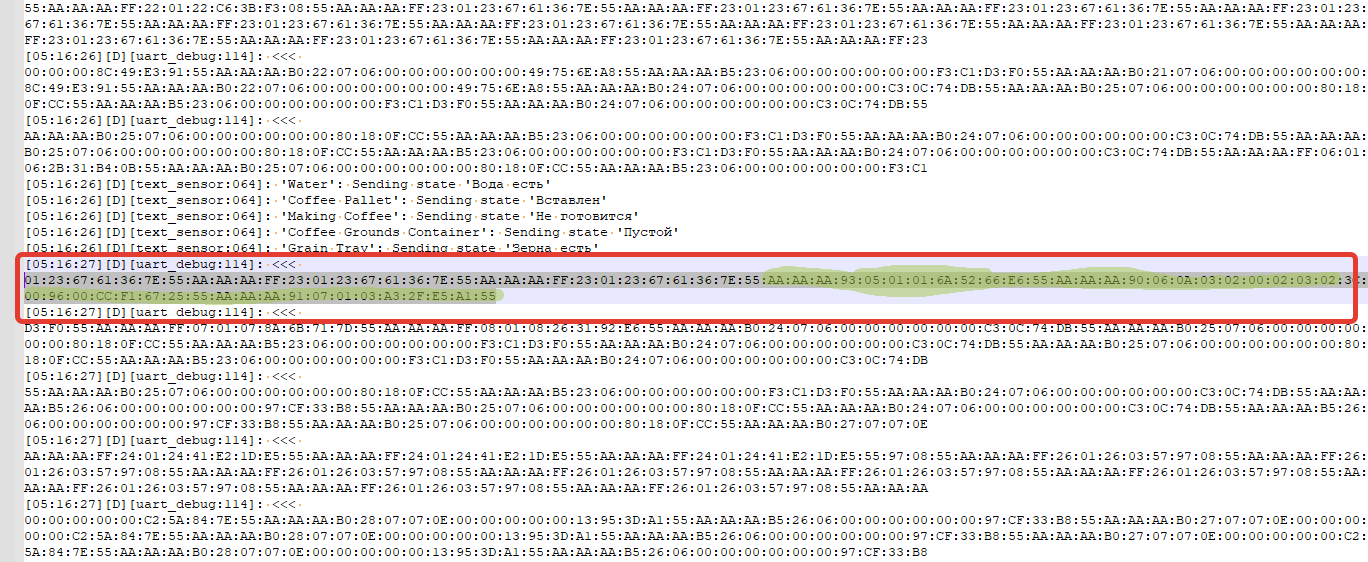
When we press the touch button on the coffee machine, I see the following data
The command being sent is AA:AA:AA:FE:00:00:C8:87:1B:40:55:AA:AA:AA:FF:00:01:00:AC:E8:5A:E6:55
Answer AA:AA:AA:FE:00:00:C8:87:1B:40:55 from the motherboard after 18.536000000 ms and after that the coffee machine turns on
This is the data from the logs when the coffee machine is turned on from the touch button and I highlighted in red where the screen sends a command and receives a response from the motherboard, and in blue, after a successful greeting, the coffee machine turns on
I tried to repeat this case, but it turns out unsuccessfully, the coffee machine does not turn on, because it does not respond. When sending a command from ESPHome AA:AA:AA:FE:00:00:C8:87:1B:40:55:AA:AA:AA:FF:00:01:00:AC:E8:5A:E6:55, then there is no response from the motherboard
Now about the scheme itself. Where did this data come from?
In the header, I posted a link to the motherboard diagram and I decided to study it and based on this diagram, I redid the wiring pinout scheme.
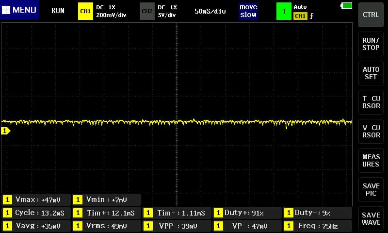
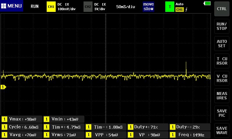
I decided to check the 4 wire that WakeUP, assuming that he could somehow turn on the coffee machine and decided to measure the signals through an oscilloscope and a logic analyzer, and that’s what I saw.
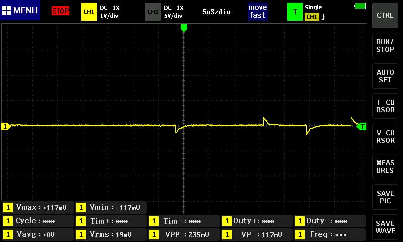
Voltage up to 200mv is supplied only when the coffee machine is turned on, and when the coffee machine is turned off, there is no voltage
Measurement through an oscilloscope
I managed to fix a signal where the voltage is applied up to 200 mv
Measurement of data through a logic analyzer
As you can see, there is no data, there are only 0, which means that only voltage up to 200mv is supplied via 4 wires
In general, I can’t figure out how to make the coffee machine turn on. I will be glad if you offer options on how to do this.


 , I found how to operate a coffee machine. To make coffee, we look in the logs for the address and functions that are listed below, this is the command to start making coffee. Start recording in the log, select the parameters we need (strength, amount of water, number of cups) to make coffee and run, then we find the command in the logs. Why is that? Because then we run what we set in the settings, so you can create a lot of different scripts with different parameters.