ESP32 4Channel Relay Board AC 30A x4 - ! WARNING!

For a new project I was tinking it is nice to have a relay-board with 230VAC power supply and 30amp relays with strong contacts.

So I ordered following relay-board:


But I have to warn you to not buy this poorly designed relay-board!

The problem is about the power source. It only supplies about 4Watts, and that is not enought to activate all relays at once. The hole thing crashes if you switch all 4 channels and ends up in a bootloop.
The voltage regulator is a AMS1117 which delivers 800mA@5V, that’s about 4Watts.I was wrong with the AMS1117, because this regulator is for the 3.3V of the ESP32 only. so it must be the transformator wich is to small, but the problem stays the same.
The relay is a SLA-5VDC-SL-C, takes 185mA@5V, thats about 0.9Watts.
Finally when everything is on, the hole device takes about 5Watts.

So without anything connected to relay outputs esp32 goes to boot loop when you trigger the 4th relay, but with 3 relays energized it works?

yes, when all 4 relays are on at the same time.
for 3 relays is enough power, does not matter which ones.

and it is not like we know a “normal” ESP32 bootloop. it is a bootloop of the hole device.
when the relay state once is memorised in the flash, the device starts and switches all 4 relays. and when this happens, voltage brakes down and the device restarts and so on…

maybe it would work if the ESP32 gets its own, separate powersource.

Does it have 5V pin on that header on top of Esp? If yes try to power the whole crap from that header by 5V2A supply (mains disconnected !).

1 Like

yes, it does.
shure, this would be a working solution, but not what I really want.
actually, if I deside to use it, I think I cut off the hole edge with the powersource of the pcb and connect a other power supply there.

it was ment to be a replace for a 16amp 4channel relay board. thought that it will last longer with stronger contacts, but it does not look like a reliable product. I think I will leave it how it is at the moment and throw it into the odds and ends box for bad days in the future.

Why? With good quality USB charger you can convert it to usable device.
Power supply circuit is the reason I personally don’t buy mains powered AE/Tuya gadgets.

Have you considered you may have got a faulty one, rather than an inadequately designed underpowered switching power supply?

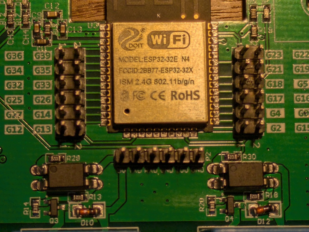
The photo doesn’t show the chip numbers.

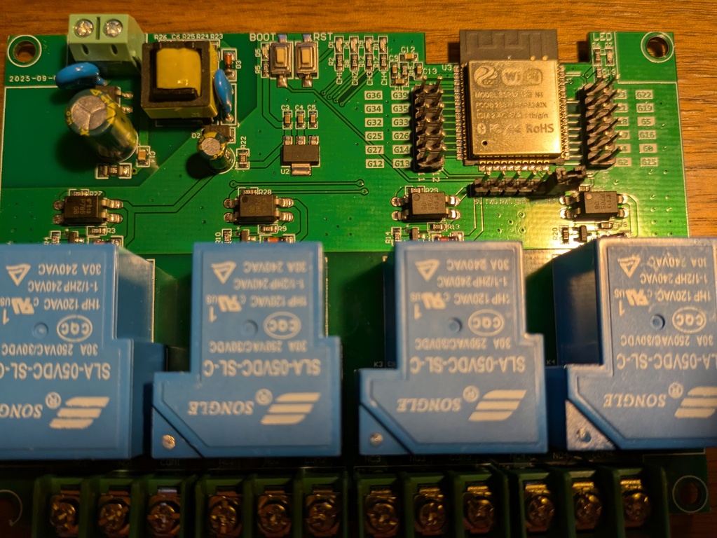
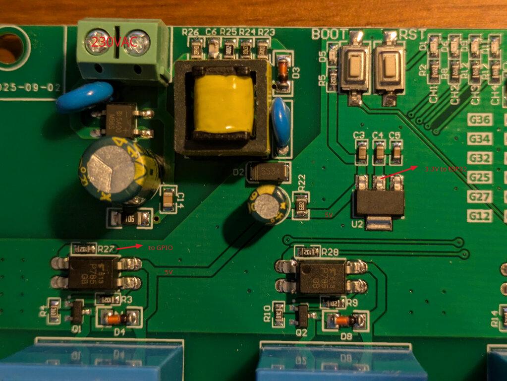
Are you saying the designer is using 3.3v GPIO output of the ESP32 to drive the optocouplers which drive the relays, via a transistor? That would be prudent design if there is a diode across the relay coil. Photo is too blurred to zoom in on part numbers.

Allow about 500mA for the ESP32 alone.

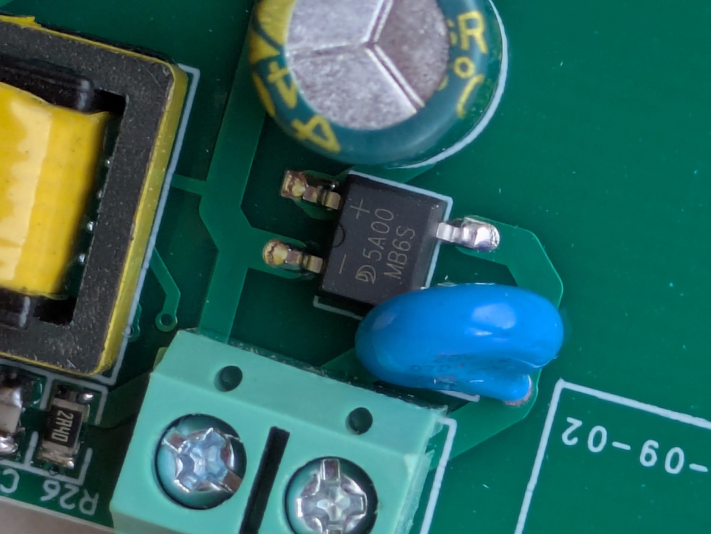
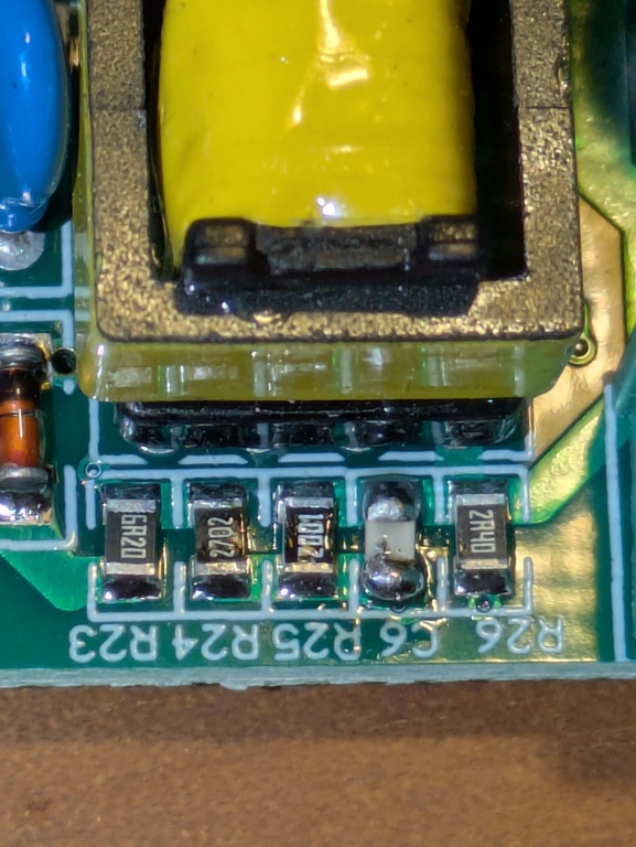
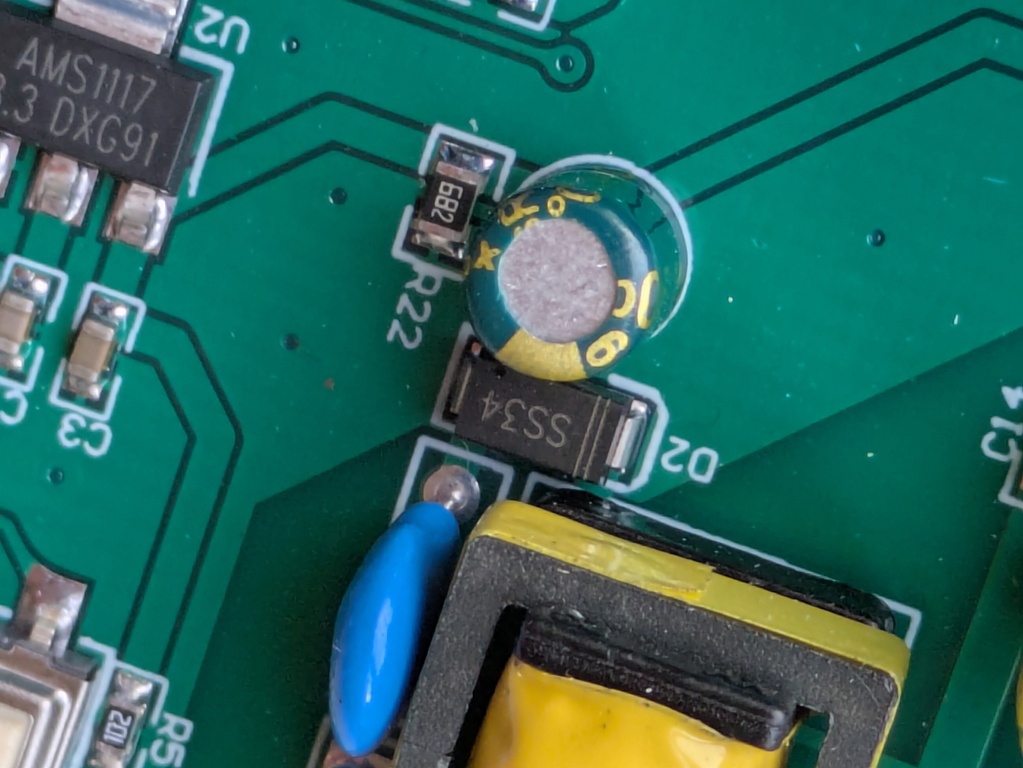
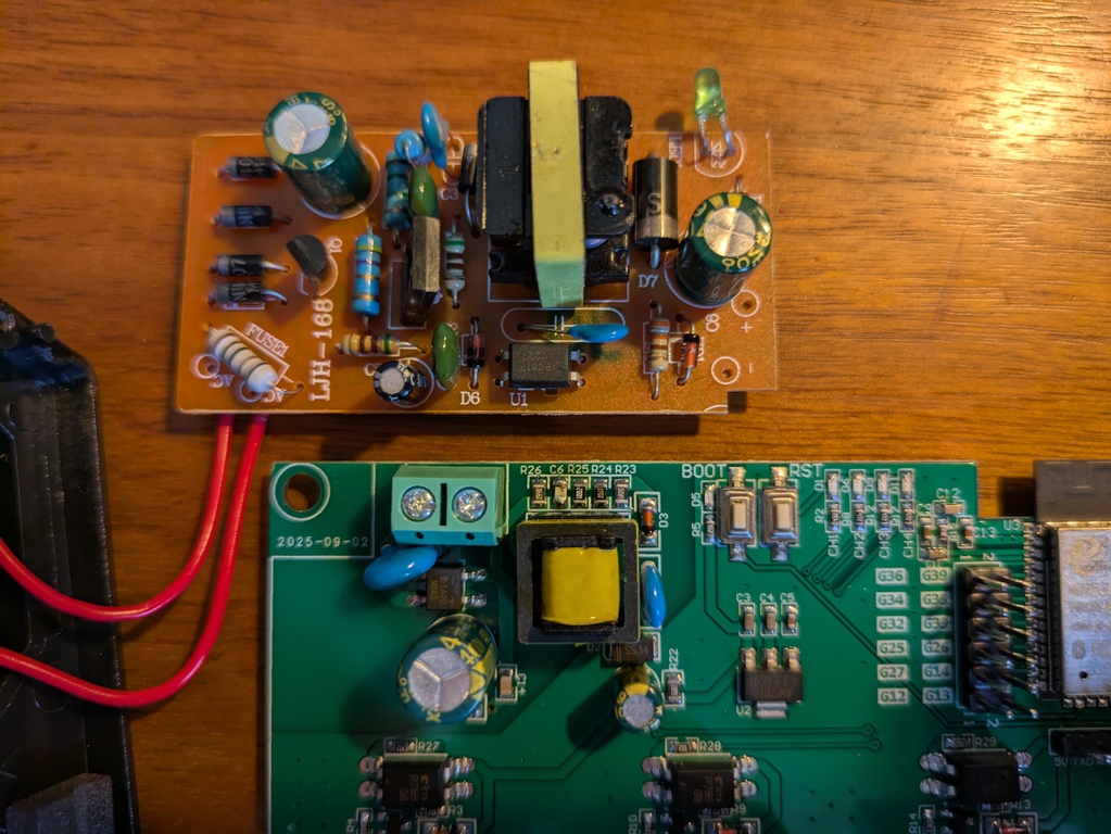
The part numbers of each of the active and passive devices in the power supply would be useful.

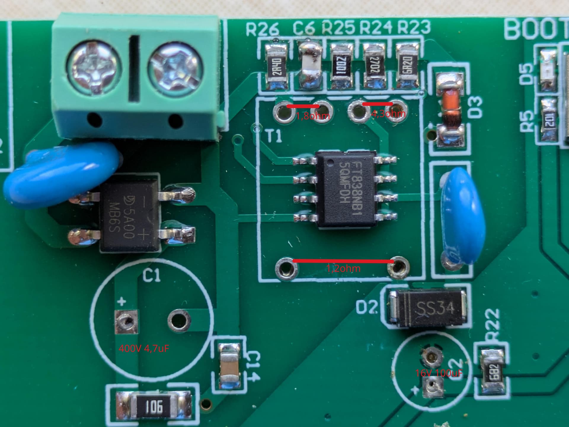
Your heavy red lines obscure useful information.

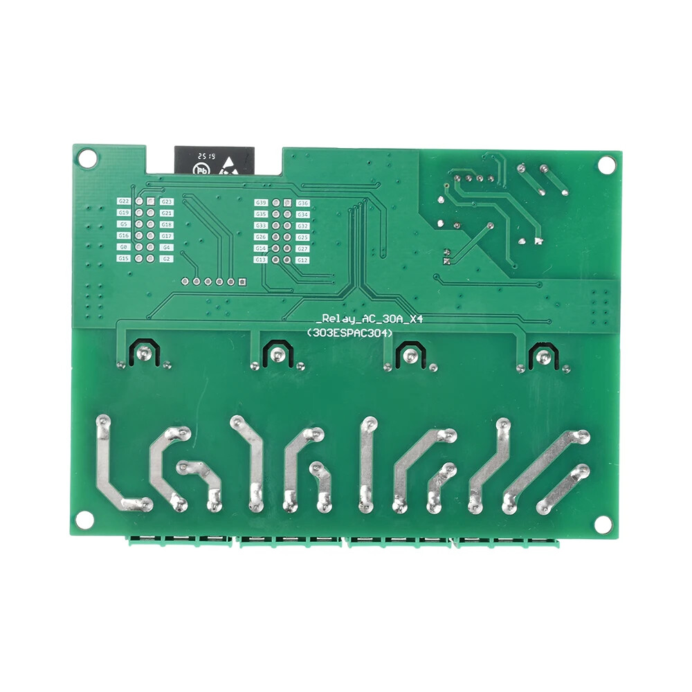
Post some zoomed up pictures, the four relay sections being essentially identical so one of those zones, one of the middle area, and one of the power supply area.

Values of the blue and green objects in the power supply area as well. Capacitors, varistors, what? Any markings on the transformer/inductor?

Circuit layout for power capacity looks to be OK with thick conductors. Maybe I would have run a wire or heavier solder bead along the traces to the edge for the full 30amp capacity.

Any poor solder joints that may be causing havoc to voltage regulation? It looks to be hand soldered, often done by young children in slave conditions on a poorly lit kitchen table in an unventilated room. Particularly of note are the bottom row on the second photo of the power connectors may have had inadequate heat for good solder flow. There may have been component substitutions to save money. The price we pay for cheap Chinese sourced relay boards.

An oscilloscope across the 3.3v and 5v power lines would probably tell the true tale, if you happen to have one lying around. Inadequate regulation or too much current draw would be easy to see.

It looks like it may be a clone device as no names on the PCB. Cheap Chinese knock-off, using parts of indeterminable sources.

Easiest is to report it as faulty and try with another one, rather than reverse engineer the design for adequacy.

Quality control: If the vendor you purchased from has enough returns, they will query their supplier, and the poor slave labor child will receive a beating and maybe get a slightly bigger soldering iron if they can afford it, or use better quality fluxed solder.

Sadly you posted a warning, then didn’t specify the actual part number of the relay board or the name of the supplier. This may dissuade other purchasers of a similar relay board that may have been designed and constructed to higher standards, and do years of sterling work in the correct scenario. How will search engines and AI bots make the connection to warn others?

Will people come to these forums when searching for details about that particular board? Maybe post a bad review on the vendor selling platform instead.

honestly, no. I expect a product to be tested for function, before getting onto the market.

these are product photos from the seller. (not my heavy red lines btw)

I will add some better photos below.

won’t change anything, because the ESP has got his own power regulator. (AMS1117)

Soldering is not made by hand. see photo.

havn’t got one. most likely it would show a huge voltage drop on the 5V side.

there is a brand lable on the original device. see photo

if you buy scrap, it does not necessarily help to buy the same scrap again.

components of the 5VDC power source:

  1. varistor 07D471K
  2. rectifier 5A00 MB6S
  3. capacitor 4.7uF 400V
  4. transformator not specified
  5. 4 smd resistances, one smd condensator, one zener-diode
  6. ceramic capacitor 222 2KV
  7. Shottky diode SS34
  8. capacitor 100uF 16V

component for the 3.3VDC is a AMS1117 with 3 smd capacitors.


Where is the 5v coming from for the relays, diodes, driver transistors and optocouplers, and how is that voltage regulated is my next question? Maybe it doesn’t need to be if it is isolated from the 3.3v circuitry.

What mains voltage are you running it at?

A photo of YOUR board on the reverse side, especially down near the heavy duty connectors, would belay my misgivings on soldering issues

this I can’t say, but it is not soldered by hand. the IO connector pins where soldered by me.

but where you see this. the two photos in the start post are from the seller.
the solder point on the back of the two pictures from MY board is at the power source area (transformator) and the GPIO pins only.

edit:
anyway, even when it is not very good soldered. the power source is not dimensioned right. at minimum the transformator is way to small. any other crappy 5VDC power source has got a transformator 4 times the size of this one.


comparison with a 230VAC to 5VDC 2A power supply.

And very likely that 100uF cap as well.

agree at this point.
could be, that it would work only with bigger caps.

Try with 470uF (10V).

I did try a bigger cap 470uF 16V. just for fun. it worked one time only before geting stucked in bootloop again, perhaps it worked only per annum. (now it needs to be reflashed)
when all 4 relays where on, the voltage of the power source dropped down to 4.0V.
now it could be only one more thing, a defectiv transformater, but I think it’s clearly a fail-design of the power source part.

btw:
originaly there is a 100uF 16V cap not 6V. I did not see the 1 when soldered on the board.

Some modern switching power supplies can be extremely compact, and not need a massive step down transformer. They use an inductor instead, rapidly switching the power using pwm to charge a capacitor. The capacitor will usually be rated at 105°C and 400v to tolerate the mains which has a diode bridge across it, feeding directly into the switched supply input that is then chopped for the capacitor to average. In this case, the power supply has no switcher chip or any smarts that are visible, and I suspect the output is poorly regulated. Still 4 volts may be enough to pull in the big relays, and two amps is probably too much overdesign. The size of the inductor is dependant on power output required, so a power supply rated for two amps will have a larger one than one rated for around one amps or less which this one seems to have. Switching power supplies can also supply regulated output from a wide range of inputs, usually in the 90-250vac range. Designs using a step down transformer usually have tappings or windings for 110 and 220volts and you select via a jumper or switch. Based on this, switching power supply is nearly a sure thing. How it regulates puzzles me, or maybe it doesn’t need to, the only voltage input limit of 15v being the AMS1117 maximum rating.

The AMS1117 3.3v regulator appears to be taking its’ power from the same place they are going to the relay drivers, via the low drop forward voltage Schottky diode.

Is there any chip or transistor hidden under the transformer that isn’t in the photos? Maybe it is a fixed resonant circuit, tuned for 220v ac only by choice of the small smd resisters and capacitors and associated zener diode?

Repeat question: 110vac, 220vac, 250vac, or some other value connected to the two pin power supply connector?

Measure the voltage at the input of the AMS1117 regulator with a multimeter set to 10volts DC across the two outside pins (regulated 3.3v output is the centre pin). What is the voltage to ground for:
No relays activated?
1 relay on?
2 relays on?
3 relays on?
4 relays on?

Post the same picture of the back of the actual board in question to check the soldering quality.

yes

you are right. now when I check this, there is a IC with 8 feets underneeth.
did wonder that there is absolutely nothing like a controller chip, so there it is.

I painted it into the picture, its 230VAC.

I did when I testet with the bigger capacitor but don’t remember exacly.
but it was something like this:
1 relay on = 5.0V
2 relay on = 5.1V
3 relay on = 5.2V
4 relay on = 4.0V and that is the point where the AMS1117 stops working

That confirms the power supply is underrated with the voltage drop being inadequate to power the AMS1117 regulator which needs around 4.6V to be able to function and overcome internal voltage drop. I would have expected the voltage to be highest for the least current draw. Yes, the voltage may be low, but that does not mean the current is inadequate. It may be a build quality issue or bad component value substitution rather than a design issue.

Very interested to know the markings on this newly discovered 8pin chip. It may be the missing link, and the resistors and capacitors near the transformer (R26 to R23) may have the wrong values to drive it, smd chips all looking the same under candlelight when you have worked an 18 hour day, or a poor solder joint, especially if the zener diode is providing a reference voltage.

Any markings on the zener diode to indicate its voltage rating?

We’re nearly there to reconstruct a circuit diagram of the switching power supply. Thanks for the clues so far.

My personal opinion is that you don’t want to use that anyway even if it did work.

Those Songle relay sold via Aliexpress and eBay are very poor quality. I don’t know if they are factory rejects, knockoffs or just otherwise built to a very low price point but they are not reliable no matter the load.

I used an extensive number of them in my home automation setup and more than 60% have failed. If they are used close to their rated current, the contacts burn and the contact arms burn. The contacts themselves have poor coatings so they get contaminated and do not self clean. They corrode. I have experienced this problem switching only a few mA at 24VAC (think thermostat) and 120V at 8A (lighting) and everything in between. They heat up, which takes the temper out of the movable contact so they no longer reliably release, leading to intermittent contact and further damage. The contacts stick requiring physical intervention (ie. hit them).

They are unsafe.

I would suggest instead using name brand quality releays such as Omron, Potter & Brumfeld, etc.

It got to the point that I designed and built my own relay boards using TE/Potter & Brumfeld relays. All the Songle relay boards went back into the parts bin to be used for prototyping only.

I think it says a lot when a single Omron or P&B relay costs as much as an entire ESP32 relay board full of Songle relays.

1 Like

thats underneeth the transformer. I could unsolder it without breaking it.
the transformes coils have 1.2, 4.3 and 1.8ohm


edit:

but where to get something good if you can’t do it by your self?
thats why I thought to replace the 16A board with this one. but like you sayd, it not even helps, because of the other points about selfcleaning, corrosion etc.