ESP32 8 channel relay & input board

Problem(s) I want to solve when dealing with fresh home build:

  • As little devices as possible, with preference of no devices in the wall units, only actual switches

  • Use of simple buttons that are consistent and not RF/brand/technology specific and have each input connected to the central unit

  • Use of smart Zigbee lights or classic ones, the system shall support both

  • HA to manage all the automations and backup if HA is down.

The key problem that made me develop my own hardware with ESP32: what do you do when HA is down and you want to control smart lights? Sure you can use direct binding, but how advance is this direct binding? Not much. Philips Hue Tap has 4 buttons but only one zigbee cluster - no possibility to distinguish and assign action to individual light.

The key concept to the solution I came up with is:

  • Connect all buttons all across the home, one to each of the inputs (230V directly)
  • Connect each smart light (or group of lights, up to you) to one output relay
  • ESP32 runs esphome
  • If ESP32 is connected to HA, then input signal is routed to the HA and HA manages the automations. HA can then control the zigbee lights, according to the user automations
  • If ESP32 is not connected to HA (ESP32 down, wifi down, HA down), then input only toggles the relay state
  • When HA boots-up, it can 1. turn on all relays to activate smart lights and 2. send necessary commands to the lights via Zigbee
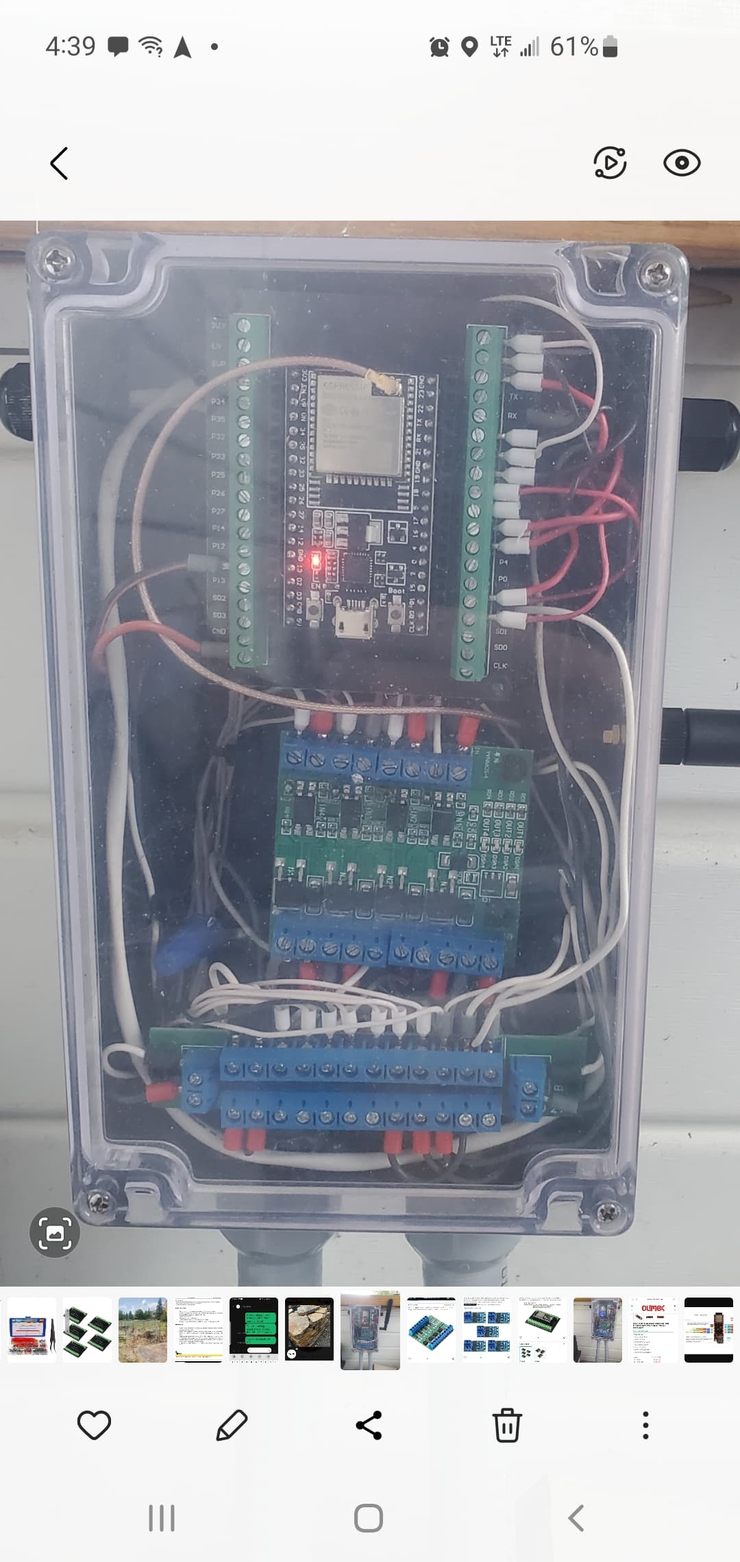
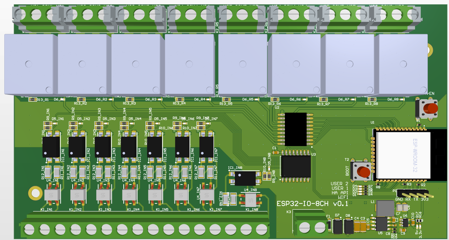
Hardware

  • ESP32 WROOM module, wifi mode
  • 8 inputs, each connected with optocoupler for isolation
  • 8 outputs, controlled directly with respective input number (when HA is down)
  • PCF8574 IO expander for input reading
  • 4 leds (2 meant for status, 2 for user)

3D view

Quickly put together. It hasn’t been produced yet nor tested yet.
The test has been made with protoboard:

  • ESP32-WROOM
  • PCF8574
  • Spice simulation for input control
  • esphome code
  • Put HA down, press the input. Result: Output toggles
  • Works as expected

ESPhome code

esphome:
  name: pfc-io-expander-test
  friendly_name: pfc_io_expander_test

esp32:
  board: esp32dev
  framework:
    type: arduino

# Enable logging
logger:

# Enable Home Assistant API
api:
  encryption:
    key: "mykey"

ota:
  - platform: esphome
    password: "mypassword"

wifi:
  ssid: !secret wifi_ssid
  password: !secret wifi_password

  # Enable fallback hotspot (captive portal) in case wifi connection fails
  ap:
    ssid: "Pfc-Io-Expander-Test"
    password: "DlRrsFjTd0ft"

captive_portal:
    
# I2C configuration
i2c:
  sda: GPIO21
  scl: GPIO22
  scan: true
  id: bus_main
  
# PFC expanders
pcf8574:
  - id: 'pcf8574_hub_input'
    address: 0x26
    pcf8575: false

# Button list
button:
  - platform: restart
    name: 'Restart'
  - platform: factory_reset
    name: 'Factory reset'

# Switches
switch:
  - id: switch_1
    platform: gpio
    name: "Output #1"
    pin: GPIO13
    inverted: true
    
  - id: switch_2
    platform: gpio
    name: "Output #2"
    pin: GPIO12
    inverted: true

  - id: switch_3
    platform: gpio
    name: "Output #3"
    pin: GPIO14
    inverted: true
    
  - id: switch_4
    platform: gpio
    name: "Output #4"
    pin: GPIO27
    inverted: true

  - id: switch_5
    platform: gpio
    name: "Output #5"
    pin: GPIO26
    inverted: true
    
  - id: switch_6
    platform: gpio
    name: "Output #6"
    pin: GPIO25
    inverted: true
    
  - id: switch_7
    platform: gpio
    name: "Output #7"
    pin: GPIO33
    inverted: true
    
  - id: switch_8
    platform: gpio
    name: "Output #8"
    pin: GPIO32
    inverted: true
    
# Inputs
binary_sensor:
  - platform: gpio
    name: "Input #1"
    pin:
      pcf8574: pcf8574_hub_input
      number: 0
      mode:
        input: true
    filters:
      - invert:
      - delayed_on_off: 50ms
    on_press: 
      then:
        if:
          condition:
            not:
              api.connected:
          then:
            - switch.toggle: switch_1

  - platform: gpio
    name: "Input #2"
    pin:
      pcf8574: pcf8574_hub_input
      number: 1
      mode:
        input: true
    filters:
      - invert:
      - delayed_on_off: 50ms
    on_press: 
      then:
        if:
          condition:
            not:
              api.connected:
          then:
            - switch.toggle: switch_2

  - platform: gpio
    name: "Input #3"
    pin:
      pcf8574: pcf8574_hub_input
      number: 2
      mode:
        input: true
    filters:
      - invert:
      - delayed_on_off: 50ms
    on_press: 
      then:
        if:
          condition:
            not:
              api.connected:
          then:
            - switch.toggle: switch_3

  - platform: gpio
    name: "Input #4"
    pin:
      pcf8574: pcf8574_hub_input
      number: 3
      mode:
        input: true
    filters:
      - invert:
      - delayed_on_off: 50ms
    on_press: 
      then:
        if:
          condition:
            not:
              api.connected:
          then:
            - switch.toggle: switch_4

  - platform: gpio
    name: "Input #5"
    pin:
      pcf8574: pcf8574_hub_input
      number: 4
      mode:
        input: true
    filters:
      - invert:
      - delayed_on_off: 50ms
    on_press: 
      then:
        if:
          condition:
            not:
              api.connected:
          then:
            - switch.toggle: switch_5

  - platform: gpio
    name: "Input #6"
    pin:
      pcf8574: pcf8574_hub_input
      number: 5
      mode:
        input: true
    filters:
      - invert:
      - delayed_on_off: 50ms
    on_press: 
      then:
        if:
          condition:
            not:
              api.connected:
          then:
            - switch.toggle: switch_6

  - platform: gpio
    name: "Input #7"
    pin:
      pcf8574: pcf8574_hub_input
      number: 6
      mode:
        input: true
    filters:
      - invert:
      - delayed_on_off: 50ms
    on_press: 
      then:
        if:
          condition:
            not:
              api.connected:
          then:
            - switch.toggle: switch_7

  - platform: gpio
    name: "Input #8"
    pin:
      pcf8574: pcf8574_hub_input
      number: 7
      mode:
        input: true
    filters:
      - invert:
      - delayed_on_off: 50ms
    on_press: 
      then:
        if:
          condition:
            not:
              api.connected:
          then:
            - switch.toggle: switch_8

Would like to hear if such hardware makes any sense to you. No prob to share the source and/or gerbers.

I hate to be a downer because this is a great accomplishment, but isn’t this essentially the same thing as the Kincony boards?

It is, except that I couldn’t find a Kincony board that allows 230V isolated inputs in 1/1 config (1 input for 1 output). The rest, I was first spending my time searching good Kincony board, yep.

The key is that only one device (one MCU) reads inputs and controls outputs, which allows local automation to toggle the outputs according to the detected signal on the input.

2 Likes

Atios SmartCore would be an alternative with native HA support, 12x relay outputs, 12x binary inputs (that support 12-24V DC and 110-230V AC). CE certified, Matter certified, Power over Ethernet, DALI for dimmable lights and non-binary sensors etc. - but of course a bit of a different price class…

EUR 600? Thanks, but no thanks, sorry. Thanks for posting the option.

For a similar project I used a 8 channel relais from Aliexpress (https://de.aliexpress.com/item/1005005970839837.html) and a D1 Mini (ESP8266) Board and also a PCF8574.
Unfortunately, the first PCF8574 I bought (the first batch) was faulty and it took me quite a while to figure it out.

Maybe HA server and DALI lights are included… :joy:

1 Like

When you have simple things like logic/automations that are as simple as (Switch State change - Turn on a light or even change colors and activate some effects) then one would probably assume that the logic/automations should actually go on the esp32 to start with and then you can avoid creating a vulnerable smart home where nothing will work if ever that day comes and HA is broken or your hardware running HA is broken which by default breaks everything relying on HA.

How advanced is it? Considering the only time you’ll be using it is in the event HA is down and which one do you think will be your highest priority? Fixing HA or replacing hardware etc, or playing with lighting colors and temperatures because of how vital it is to the system and being thankful you at least have lights and can control their basic features at a bare minimum. There’s also other possibilities that can be used and not just direct binding but, that will largely depend on how you design your smart home and what devices you use and whether you have allowed for multiple wireless communication protocols or if you’ve irrationally stuck to only allowing devices into your system that use 1 specific protocol and really limit your options when problems like this pop up.

Ya, I couldn’t tell you anything about those items because I stay away from as many devices that force users to use a ridiculous hub or they intentionally make their products so they don’t play nice with other brands or ecosystems. I mostly use Kauf smart bulbs in the few flaces i even use them and they come already flashed with Esphome so ther’s no need to deal with self-inflicted problems at any point because they all play nice together 100%

That kind of reinforces my point above about brand name devices like a simple button or 4 buttons all in 1 group or whatever. To each his own but, i would argue that using Phillips Hue overpriced buttons probably wasnt the best decision seeing as how we’re just talking about a button or several buttons which is the most basic thing you can do with a microcontrller or whatever your using for communication. A button is a digital signal, either High(ON) or LOW(OFF) and using something like Esphome would keep you from getting bogged down with troubleshooting little things like this.

Now your starting to implement some good strategies! Me, personally I would suggest that you look into all the devices that Shelly offers because they play well with others, they have capabilities for multiple types of wireless communication and come standard with capabilites for things like using MQTT, REST, Webhooks, and some are zigbee, some use BT and wifi and some that use BT also serve as BT proxies additionally, they’re very very useful devices and have a large product catalog.

No, that is not true. The physical signals coming into the esp32 from things like buttons/switches are firest processed by that esp32 and if someone foolishly created all the logic and automations for those buttons in HA then, ya it will go to HA and if HA is down then they just get sent into a signal black hole… This is why creating your logic and/or automations on each of the esp boards is recommended because then it doesn’t matter if HA is down or at least to the extent that even your automation relies on doing things like using HA imported sensors to that esp32, then those things wont work but, the thing your trying to do is to not loose 100% of ability to use the lights or whatever. Maybe there is a situation where you can’t do any advanced configuration through Esphome when HA is down but, you wont be sitting there in the dark being mad about it because, you’ll at least have all the basic controls available untill you can get your HA running again.

That is 100% possible and can actually be accomplished physically from the way you do the wiring with the switches and relays.

I meant to ask this earler but, why are you trying to use smart led’s or regular led’s and wanting to control them using relays? You don’t need any relays at all for this and for regular led’s or all led’s that aren’t addressable then usng a relay is not just someones opinion of being not needed but, they are actually the wrong device to use without a doubt because you can’t dim led’s through a relay… You need mosfets or mosfet modules like this.
4 channel mosfet module

Here’s my led controller I made for controlling all my outdoor landscape led’s, up lighting, accent lighting, and water feature lighting. This is a stacked group of 4 channel modules for controlling 12 lights.

Why are you all using relays to turn ON/OFF led lights to begin with? Unless they are all powered by mains 110/220VAC then idk why anyone would use relays.

I’ve never controlled individual LEDs with a relay before, what made you think that? My 8-way relay controls the components of my home theater system and also a floor lamp (with a motion detector so I don’t have to constantly find my way out of the room in the dark). For higher AC voltages and higher power outputs, I also use solid-state relays.
Relays are a simple, inexpensive, and relatively safe way to switch any current and voltage (within the relay’s specifications, of course) and isolate them from the control electronics. With solid-state relays, MOSFETs, thyristors, TRIACs, and transistors, you have to consider exactly what you want to switch (only AC voltage, only DC voltage, both, and what size).

Uhhh… It may have been from a verbatim statement to the contrary.

Well, you didn’t specify that you had used them for something unrelated to the topic of this post which was Buttons and Relays for controlling led lights. When someone sais, “For a similar project I used a 8 channel relais from Aliexpress” and seeing as how no one in here can read minds, then we automatically assume that you’re also talking about using relays for controlling led’s because what else would anyone assume you are talking about other than what we are all talking about?

So, really it’s not very similar at all and the one thing your project has in common with this is you both used an 8 channel relay module which… That’s kinda like seeing a Boeng 777 plane and stating, “I have one similar to that plane” and come to find out the only thing similar is one actually flies and the other one, a child gets in and pedals up and down the driveway…

No, the relay hardware setup is almost identical to my project, except that I separated the relay board and controller board and used standard products from Aliexpress. I think this solution is simpler and more cost-effective than designing own hardware. The custom solution obviously has the advantage of being able to choose better components, but it is also comparatively more complex (although the work is already done). The hardware board presented here is suitable for switching any device up to approximately 240V AC/10A and probably 30V DC/10A. It could also switch a socket connected to a floor lamp or other device.

Why?

Some considerations you should do with relays as well. Like DC voltage or capability for inductive loads…

I already had sticking issues with the regular relays until I installed additional RC snubbers. I also heard a lot about durability issues with relays in another forum. Based on my experience, I wouldn’t, for example, implement garden irrigation with regular relays unless I also installed a flow monitor with a special shut-off valve.
Solid-state relays can’t stick and should be much more reliable (my first one won’t be running for a few weeks, though; so far, I’ve only used regular relays). However, most of them only work properly above a certain minimum AC voltage and minimum load, otherwise it quickly becomes expensive…

Both have pro and cons. Rc-snubber is almost must with big inductive loads.
Solid state relays are expensive, except “fake” ones, like 90% of those you find in AZ or AE.
100A SRR with 20A triac inside, thin traces and insufficient heatsink is bad combination.

The relays on all my motion detectors around the house failed after 8-12 years. For my own build, I’ve now opted for a solid-state relay (although this is a bit over-engineered, as the relay can switch 1,000 times faster than the light ever switches and can handle ten times the load). I hope I won’t have to replace this relay in my lifetime.

I bought two Fotek SSR-25DA relays from Aliexpress, which initially seem good. They’re housed in a solid metal housing and secured to the housing with a thermal pad. I also installed an additional temperature sensor inside the housing. With the expected low load of less than 4A, there shouldn’t be any temperature issues. We’ll see how they perform.

Thanks for sharing. The initial idea I had is that relays will very rarely switch in my case at least.

With that load chances are high that you don’t face problems even if your Fotek is likely fake. You could check the leakage current though (if relevant for your circuit).

I don’t remember the exact values ​​(I wrote them down somewhere), but with the test setup, I couldn’t measure any relevant leakage current (the datasheet said < 5mA, and it must have been significantly lower than 5mA).
To be safe, I switched the relay with a transistor because I wasn’t sure how much current would be drawn at a 5V switching voltage. As far as I can remember, the switching current was also below the D1 Mini limit, but I kept the transistor in the final circuit to protect the D1 Mini.

You could not switch anyhow at 5V with Esp in the first place.
And 3.3V is not sufficient to reliably switch that relay.
So for sure you needed your transistor.
The current is not high, because the optocoupler max current is 60mA and Fotek max voltage is 32V. The current at 5V is about 5mA (red LED and 500R in series with optocoupler).