ESP32 - alert on power outage

The short version:
I have setup an esp32 that can raise an alert should the mains power go out. Ideally requires an esp that has both a usb port and a battery socket plus a pin that has voltage to it only when power is being provided via usb - although likely all of that could be done by some deft soldering on different esp boards that don't have all of that.

The longer version:
I have a number of esp based devices in my house, some of which I deem fairly critical. For example, ones that measure the temperature of the freezer. The issue is that if the fridge/freezer loses power generally that also means that the esp device is no longer monitoring the freezer.

I'd like to know how warm the freezer got to before the power came back (so I know if the food has to be thrown out). I'd also like to get alerted should someone accidentally turn the power off to the fridge/freezer & esp device (which has happened) - so I can do something about it.

This is just one use case scenario - I am sure that there are many more out there. For example, I have various esp devices scattered about the house used for ble proximity tracking that could also provide alerts should one specific power circuit lose power due to a safety fuse trip. Note - keep in mind that all my network kit is supported by UPS so if the power goes out, the network stays up for a while so alerts will keep firing.

I had already given some esp devices effectively mini UPS's - basically plug the esp into a usb battery pack that is in turn connected to a wall charger. Worked fine, and a good way of using any old 18650 cells laying around, but hard to monitor if there is an issue.

How to do it. I had a hunt through the forums and couldn't see any examples of people doing it. Found a number of people asking about something like this, with various suggestions using external AC relays, and a few other options like using Ring extenders, but it all seemed a bit complex and expensive. Quite likely I just missed an example of someone doing just this, but I seemed to be on my own. Fine. My theory - setup an esp that is powered via usb but that also has a battery. When the power goes out, the device runs off the battery, and detects that there is no power in the 5v rail so sends an alert. When power is restored, it can send an alert about that.

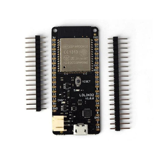
I decided to try a Lolin D32 - it has been around for ages, is cheap, and has both USB and battery sockets. As a bonus, I had a spare to play with. It also has a pin marked "USB" that, when the esp32 is getting power from the USB port power is sent to that pin. I figured that if I connected the USB pin to one of the pins that would be able to toggle it high or low as power turned on/off via the usb port.

So, time to code. Turned out to not be too hard. Pretty quickly I was able to test the thing, and it worked first time. I use Bermuda for proximity tracking so my code is basically for one of those - obviously you could use the basics for any device you have out there - just maybe changing the GPIOs to match depending on what you are using.

# Compiled and tested on esphome 2025.2.2 and HA 2025.3.0
# Notes:
#  * need to jumper between USB pin and pin 16 - when USB power is connected, power goes to the USB pin and sets pin 16 high
#  * Using a Lolin D32 as cheap and has built in battery socket
#  * Note that need to check polarity on battery - in my case frequently they are reversed.

substitutions:
  name: ble03
  friendly_name: ble03
  devicename: ble03
  location: master

esphome:
  name: ${name}
  friendly_name: ${friendly_name}
  min_version: 2024.6.0
  name_add_mac_suffix: false
  project:
    name: ninkasi.ble
    version: '1.1'
  comment: BLE Sensor LOLIN D32 $location
  platformio_options:
    build_flags:
      - "-D CONFIG_ADC_SUPPRESS_DEPRECATE_WARN=1" # Putting this in temporarily to remove warning ā€œlegacy adc calibration driver is deprecated" message during compilation - https://github.com/esphome/issues/issues/5153#issuecomment-1847547482

esp32:
  board: esp32dev
  framework:
    type: esp-idf
    version: recommended
    # Custom sdkconfig options
    sdkconfig_options:
      COMPILER_OPTIMIZATION_SIZE: y
    # Advanced tweaking options
    advanced:
      ignore_efuse_mac_crc: false

# Enable logging
# Change to avoid "Components should block for at most 20-30ms" warning messages in the log - an issue since 2023.7.0
# Not really a breaking change - it's an issue I suspect due to the device being slow and this error previously
# simply not being reported
logger:
  baud_rate: 0  # disable serial uart logging to maybe save a little ram
  logs:
    component: ERROR

api:
  encryption:
    key: !secret esphome_encryption_key

ota:
  password: !secret ota_password
  platform: esphome

wifi:
  networks:
  - ssid: !secret wifIoT_ssid
    password: !secret wifIoT_password
    priority: 2
# Backup SSID just in case
  - ssid: !secret wifi_ssid
    password: !secret wifi_password
    priority: 1
  # Enable fallback hotspot (captive portal) in case wifi connection fails
  ap:
    ssid: "$devicename Fallback Hotspot"
    password: !secret ota_password

esp32_ble_tracker:
  scan_parameters:
#    continuous: True
    active: True
    interval: 211ms # default 320ms
    window: 120ms # default 30ms

bluetooth_proxy:
  active: true
  
sensor:
  - platform: wifi_signal
    name: "WiFi Signal Sensor"
    id: wifisignal
    update_interval: 60s
    unit_of_measurement: dBm
    accuracy_decimals: 0
    device_class: signal_strength
    state_class: measurement
    entity_category: diagnostic
  - platform: copy # Reports the WiFi signal strength in %
    source_id: wifisignal
    id: wifipercent
    name: "WiFi Signal Percent"
    filters:
      - lambda: return min(max(2 * (x + 100.0), 0.0), 100.0);
    unit_of_measurement: "Signal %"
    entity_category: "diagnostic"
  - platform: uptime
    id: uptime_s
    name: "$devicename Uptime"
    update_interval: 60s          
  - platform: template
    name: $devicename free memory
    lambda: return heap_caps_get_free_size(MALLOC_CAP_INTERNAL);
    icon: "mdi:memory"
    entity_category: diagnostic
    state_class: measurement
    unit_of_measurement: "b"
    update_interval: 60s
# Define the battery pin (GPIO35) as an ADC sensor
  - platform: adc
    pin: GPIO35
    name: "Battery Capacity"
    id: battery_capacity
    icon: mdi:battery-medium
    unit_of_measurement: "%"
    accuracy_decimals: 0
    attenuation: 12db
    update_interval: 60s  # Update every 60 seconds (adjust as needed)
    filters:
      - multiply: 2.0
      - median:
          window_size: 7
          send_every: 7
          send_first_at: 7
      - throttle: 15min
      - calibrate_polynomial:
         degree: 3
         datapoints:
          - 0.00 -> 0.0
          - 3.30 -> 0.0
          - 3.35 -> 5.0
          - 3.39 -> 10.0
          - 3.44 -> 15.0
          - 3.48 -> 20.0
          - 3.53 -> 25.0
          - 3.57 -> 30.0
          - 3.62 -> 35.0
          - 3.66 -> 40.0
          - 3.71 -> 45.0
          - 3.75 -> 50.0
          - 3.80 -> 55.0
          - 3.84 -> 60.0
          - 3.88 -> 65.0
          - 3.92 -> 70.0
          - 3.96 -> 75.0
          - 4.00 -> 80.0
          - 4.05 -> 85.0
          - 4.09 -> 90.0
          - 4.14 -> 95.0
          - 4.20 -> 100.0
      - lambda: |-
          if (x <= 100) {
            return x;
          } else {
            return 100;
          }

    on_value_range:
      # Trigger an action if the battery voltage goes below a threshold (e.g., 3.3V)
      - above: 30
        then:
          - logger.log: "Battery voltage is above threshold"
      - below: 30
        then:
          - logger.log: "Battery power detected (below threshold)"

# Optional: Set a custom threshold to trigger actions, e.g., battery level below 3.3V
binary_sensor:
  - platform: template
    name: "Low Battery"
    lambda: |-
      if (id(battery_capacity).state < 30) {
        return true;
      } else {
        return false;
      }
    on_press:
      - logger.log: "Battery is low"
    on_release:
      - logger.log: "Battery is back to normal"

# Define the GPIO pin connected to USB power detection
  - platform: gpio
    pin: 16  # GPIO pin connected to USB power
    name: "USB Power Status"
    device_class: power
    filters:
      - delayed_on: 100ms
      - delayed_off: 100ms
    on_press:
      # Action to take when USB power is disconnected (i.e., running on battery)
      then:
        - logger.log: "Running on battery power"
    on_release:
      then:
        - logger.log: "Running on USB power"
        # Optionally, trigger actions for when USB power is present

So if you want to give this a go, you just compile the code (changing to suit your device), send it to your esp32, connect the jumper wire, and hook up a battery & usb charger. Aside from devices that have no wiring, this has to be one of the simplest wiring diagrams ever. Run dupont jumper wire from USB pin to pin 16 (originally used 5 and was totally fine, but changed to 16 to avoid strapping pin warning messages)
Note: Do not do this! Add some resistors or a buck converter to drop the voltage to 3.3v or lower to avoid the risk of damaging the board.

. Enjoy. :slight_smile:

Notes:

  • Now I know it works, I'm probably going to convert a number of my sensors over to this. I don't need to do all of them, but some key ones definitely.
  • I am sure there are many different esp devices that could be used for this. Feel free to try something else.
  • This is still early days - I have not run this for an extended period so cannot confirm as to how reliable it is, but so far it's been good
  • Eventually the battery will die I suspect, given that it is on charge constantly although the Lolin does appear to turn off charging for a while - monitoring it to see what level the battery needs to drop to before it starts charging again, but even so it's not great.
  • Although small, if the battery does fail there is a risk - if also small - that it will do so in a spectacular fashion involving flames so best not to hide this sort of thing in a roof cavity.
  • I've used a 1200 mAh battery because that's what I had - this easily supports the esp32 running as a ble tracker for over 8 hours. Unless it's being used to monitor a fridge/freezer, could probably use a much smaller battery.
  • You could have the esp raise alerts directly, maybe flash lights etc, but I tend to prefer putting all that into automations so I can manage them separately. That's just me - again, feel free to do it differently. An example automation would be (obviously changing to match your details):
alias: Alert - ble03 has detected a power outage!
description: ""
triggers:
  - trigger: state
    entity_id:
      - binary_sensor.ble03_usb_power_status
    to: "off"
    for:
      hours: 0
      minutes: 0
      seconds: 5
conditions: []
actions:
  - data:
      title: ble03 has detected a power outage!
      message: ble03 has detected a power outage!
    action: persistent_notification.create
  - metadata: {}
    data:
      message: ble03 has detected a power outage!
      title: ble03 has detected a power outage!
      target: [email protected]
    action: notify.example_com
  - action: notify.mobile_app_pixel_9_pro
    data:
      message: ble03 has detected a power outage!
      title: ble03 has detected a power outage!
mode: single

FYI Did some playing with the code to get a more accurate read on the battery as well as remove some compilation warnings. Have now updated the code above.

Very elegant solution. I’ve got ESPHome-based Bluetooth Proxy devices near BLE temperature sensors that are inside freezers & fridges. (I love the Switchbot Indoor/Outdoor Hygrometers for that.) This could indeed track the temps during power outages.

And even if I don’t need an ESP/battery setup in one place where HA can detect power failure of other (mains-powered) devices, and BLE reporting can continue thru a POE-powered BT Proxy, you’ve certainly given me ideas for additional monitoring automation.

Interesting. Glad it’s working for you! I initially tried some battery powered sensors, but had issues with signal range and battery life. This was years ago and not sure the Switchbot stuff was available then. Anyhow I eventually decided to use ds18b20 sensors that come in stainless steel probes and ran the wires direct to an esp stuck to the outside of the fridge/freezer. :slight_smile:

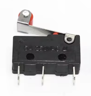
Oh, many years before I started using esphome, I setup physical switches connected to the door(s) so I can raise an alert if one is left open for too long.


Have two fridges - one plays the Imperial March from Star Wars, the other plays Ah-Ha ā€œTake on meā€. I made those using arduino pro minis with passive buzzers to play midi files - very nasty noise, surprisingly loud, and works really well to provide incentive for even the laziest teenager to get up and close the door. Thought about replacing them with ESPs, but could not replicate the sound. :rofl:

Just curious- What did you use with ESPs to try replicating sounds? I’ve been meaning to try an ESPHome with passive buzzer, using RTTL. Is that likely to be usable sound?

Yeah, I can’t say enough good about the Switchbot BLE ā€œindoor/Outdoor Thermo-Hygrometersā€. They are so solid in reaching my BT Proxy BT devices. I thought one had a signal issue, and moved a BT Proxy nearby. But turned out that was the fault of the BT Proxy that was already supposed to be covering that end of the house. I don’t know how the Switchbot units get thru the metal cabinets, but they do (maybe thru door seals?). Device specs say BT range is 394 feet.

I’ve got another one outdoors, on the outside of a metal building, and that one works fine too. They are amazing. And cheap. And IP65 waterproof.

Good luck with that. I tried and failed to work out how to do it properly with an esp device. Best option at the time seemed to be to use an actual speaker, but it really didn’t nail that horrible greeting card noise I was aiming for. That’s why mine are still using arduino pros as seen here. With RTTL support now it definitely seems possible so I might revisit.

…and the answer is - yes. Some test code follows. Hooked a passive buzzer up to an esp32 and it worked. I had a three pin job and found it was a little louder when I connected the vcc pin, but other than being a bit quieter it works fine just hooked up to ground and data.

output:
  - platform: ledc
    pin: GPIO17
    id: buzzer_output

rtttl:
  output: buzzer_output

switch:
  - platform: output 
    name: 'buzzer'
    id: buzzer
    output: buzzer_output
    on_turn_on: 
      then:
         # Star Wars
#        - rtttl.play: "Imperial:d=4, o=5, b=100:e, e, e, 8c, 16p, 16g, e, 8c, 16p, 16g, e, p, b, b, b, 8c6, 16p, 16g, d#, 8c, 16p, 16g, e, 8p"
        # Star Wars Imperial Long
#        - rtttl.play: "ImpMarch:d=8,o=5,b=120:4a4,4a4,4a4,f.4,16c,4a4,f.4,16c,2a4,4e,4e,4e,f.,16c,4g#4,f.4,16c,2a4,4a,a.4,16a4,4a,g#.,16g,16f#,16e,f,p,a#4,4d#,d.,16c#,16c,16b4,c,p,f4,4g#4,f.4,16a4,4c,a.4,16c,2e,4a,a.4,16a4,4a,g#.,16g,16f#,16e,f,p,a#4,4d#,d.,16c#,16c,16b4,c,p,f4,4g#4,f.4,16c,4a4,f.4,16c,2a4"
        # Take on me
        - rtttl.play: "TakeOnMe:d=4,o=4,b=160:8f#5,8f#5,8f#5,8d5,8p,8b,8p,8e5,8p,8e5,8p,8e5,8g#5,8g#5,8a5,8b5,8a5,8a5,8a5,8e5,8p,8d5,8p,8f#5,8p,8f#5,8p,8f#5,8e5,8e5,8f#5,8e5"

    on_turn_off:
      then:
        - rtttl.stop: 

My sample code just plays the selected tune once when you turn the switch ā€˜on’. When you turn the switch ā€˜off’ it will stop the tune if it’s still playing. So now I just need to change the code to loop the annoying tune and then I can migrate my old fridge/freezer arduino based alarms to esp’s and as an added bonus can even set them up to start complaining if the temperature is out of range.

As an aside, I bought two different types of passive buzzers from two different suppliers from Aliexpress. I’m glad I did, as one of them - although the listing description and packaging both said that they were passive - was actually active. The larger ā€œHigh Quality Passive Buzzer Moduleā€ style that I’ve used in the past was the bust, but the smaller ā€œKeyes Passive Speaker Buzzer Moduleā€ worked fine.

…and, here’s an update to that code:

output:
  - platform: ledc
    pin: GPIO17
    id: buzzer_output

rtttl:
  output: buzzer_output

button:
  - platform: template
    name: "Take On Me Button"
    on_press:
      - logger.log: Take On Me Button Pressed
      - rtttl.stop: # Stop anything else that might be playing
      - repeat:
          count: 5
          then:
            - rtttl.play: "TakeOnMe:d=4,o=4,b=160:8f#5,8f#5,8f#5,8d5,8p,8b,8p,8e5,8p,8e5,8p,8e5,8g#5,8g#5,8a5,8b5,8a5,8a5,8a5,8e5,8p,8d5,8p,8f#5,8p,8f#5,8p,8f#5,8e5,8e5,8f#5,8e5"
            - while: # Let's not interrupt things whilst it's playing
                condition:            
                  rtttl.is_playing
                then:
                - delay: 1s
  - platform: template
    name: "Imperial March Button"
    on_press:
      - logger.log: Imperial March Button Pressed
      - rtttl.stop: # Stop anything else that might be playing
      - rtttl.play: "ImpMarch:d=8,o=5,b=120:4a4,4a4,4a4,f.4,16c,4a4,f.4,16c,2a4,4e,4e,4e,f.,16c,4g#4,f.4,16c,2a4,4a,a.4,16a4,4a,g#.,16g,16f#,16e,f,p,a#4,4d#,d.,16c#,16c,16b4,c,p,f4,4g#4,f.4,16a4,4c,a.4,16c,2e,4a,a.4,16a4,4a,g#.,16g,16f#,16e,f,p,a#4,4d#,d.,16c#,16c,16b4,c,p,f4,4g#4,f.4,16c,4a4,f.4,16c,2a4" # play once
      - while: # Let's not interrupt things whilst it's playing
          condition:            
            rtttl.is_playing
          then:
          - delay: 1s
      - while: 
          condition:
            switch.is_on: repeat
          then:
          - logger.log: "Repeat is on, keep playing!"
          - rtttl.play: "ImpMarch:d=8,o=5,b=120:4a4,4a4,4a4,f.4,16c,4a4,f.4,16c,2a4,4e,4e,4e,f.,16c,4g#4,f.4,16c,2a4,4a,a.4,16a4,4a,g#.,16g,16f#,16e,f,p,a#4,4d#,d.,16c#,16c,16b4,c,p,f4,4g#4,f.4,16a4,4c,a.4,16c,2e,4a,a.4,16a4,4a,g#.,16g,16f#,16e,f,p,a#4,4d#,d.,16c#,16c,16b4,c,p,f4,4g#4,f.4,16c,4a4,f.4,16c,2a4"
          - while: # Let's not interrupt things whilst it's playing
              condition:            
                rtttl.is_playing
              then:
              - delay: 1s
          
  - platform: template
    name: "Stop Button"
    on_press:
      - logger.log: Stop Button Pressed
      - rtttl.stop: # Stop anything else that might be playing

switch:
  - platform: output 
    name: 'repeat'
    id: repeat
    output: buzzer_output
    on_turn_on:
      then: 
      - logger.log: Repeat is ON
    on_turn_off:
      then:
        - logger.log: Repeat is OFF
        - rtttl.stop: 

Basically shows a couple of examples where you can play a tune a few times, play something else on infinite loop, or interrupt whatever is playing.

…and for those using esp8266, just need to change the output

output:
  - platform: esp8266_pwm
    pin:
      number: D6
    id: buzzer_output

For my freezer door, I just setup an automation that - in the event that the door is left open for ā€˜nn’ seconds it switches on the repeat, and fires off the alarm. When the door is closed, another automation ā€˜presses’ the stop button.

oh, and wow after converting over one of my old freezer alarms I’ve found that the old passive buzzer is way louder than the new ones I got. Weird, but I guess that’s the luck of the draw.

Hello,

This is a far fetch but I am building the exact same setup for my project but I couldn't get my hands on the LOLIN D32. Instead, I am using a LOLIN V1 Board and confused how to set it up since there is no VUSB or VBUS Pin and everywhere I read it says it is not safe to connect the 5v pin to any GPIO to monitor the HIGH/LOW.

Could u help me out here ?

This example is terrible. Not only do they have 5v power going to a pin that takes 3.3v maximum but even their battery monitoring thinks a 3.7v will get to 4.2v and they seem to misunderstand the battery charger circuitry on their board.

At a minimum use a diode to drop the voltage from the USB line to the GPIO.

Good pickup re pumping 5v into a gpio pin - no idea why I didn't think of that! I'll update the instructions to include either a buck converter or resistors to drop the voltage to 3.3v. I haven't had any issues with the Lolin board, but that may simply be dumb luck or perhaps because it's not using it to drive anything - but either way it's really bad practise....

As for the 3.7v battery going to 4.2v, that's how they work. A standard 3.7v lipo battery voltage ranges from about 3.2 (flat) to 4.2 (full), with 3.7v being their nominal charge.

Cheers

Firstly, yep don't do what I did! Need to drop the voltage to 3.3v or less using a buck converter or 10 kΩ and a 20 kΩ resistors. I'm going to update the instructions. As for no vbus pin, what I'd do is hack the USB cable - run a wire from the cable through the resistors or buck converter to the gpio pin. I'm on my mobile at the moment, but will update the instructions above as soon as I can.

Yea I wasn't going to do it right away but I was wondering how did that even not fry the board already. I am new to the world of microcontrollers and I went around asking everyone if this is fine and everyone said no so I eventually dropped it and made up my mind to add a voltage divider in between.

Thank you. This setup made me feel excited since the idea of using a breadboard and resistors capacitors made it feel complex and messy. However I have arrived at the conclusion that u are one lucky man and did not fry your board and I won't be taking that chance lol.

I have decided to go ahead and build a voltage divider since that is the only thing that is required extra as the power path module and battery charging module is in-built on the LOLIN32's.

I am also wondering if the reason u did not face any issues was due to the inbuilt voltage divider on the lolin somehow reduced ur voltage from the VUSB to the GPIO because otherwise I have no idea how this worked.

Yep, pretty much what I'm thinking. I actually have at least three of these disasters that have been happily running without issues for over a year.... maybe just maybe it's something specific to the Lolin that is keeping the magic smoke inside, but even if that's the case for best practices will work on as simple a V2 as I can this weekend. I have a stack of buck converters I could use but - in the spirit of making this as easy as possible - I think I might Frankenstein some Dupont cables with resistors to drop the voltage instead, which will in turn make it easy to upgrade existing ones in situ.

I think it has to do with something about the LOLIN. But I measured the 5v port from my LOLIN32 V1 but sadly it is outputting a solid 5v. But either way, I have setup a voltage divider and hoping that it outputs the reduced voltage that is safe to connect to a GPIO pin.