The story
During the winter time I usually feed wild birds, but unfortunately while working out of my place I can’t see what is going on in my bird feeder. So the solution was to make some photos automatically when I’m away.
How does it work?
Most of the time camera stays in deep sleep mode witch is very energy efficient that means that board does not consume a lot of energy. In the same time solar panel charges the battery. When PIR event occurs camera wake’s up, connect to local wi-fi, make photos and sends them to defined FTP server. If there is no motion again , it goes to sleep. What’s more every 30 minutes camera reports it’s status to mqtt and shows current temperature and wi-fi signal strength.
Bill of materials:
- esp32 camera module
- programmer FTDI
- wi-fi antenna (IPEX to SMA)
- sr 501 pir sensor but any other pir sensor should do the job
- 1865 battery 3000mah
- ds18b20 – one wire temperature sensor
- 1865 battery holder
- on-off switch
- solar panel – 1W, 5,5V, 95mmx95mm
- li-poly charger - TP4056 5V USB
- dc converter - STEP-UP MT3608
- ds18b20 – one wire temperature sensor
Step 1 - program the board
Program the board with attached code sketch - .ino.
Before, change settings inside the code especially:
char ftp_server[] = "192.168.1.XX"; //your FTP IP
char ftp_user[]   = "XX"; //your FTP user name
char ftp_pass[]   = "XXX"; //your FTP pass
const char *ssid =     "XXXX";         // Put your SSID here
const char *password = "XXXX";     // Put your PASSWORD here
const char* mqttServer = "XXX.XXX.X.XX"; // MQTT broker IP, home-assistant
const int mqttPort = 1883; // MQTT port (domyślnie 1883)
const char* mqttUser = "XX"; // MQTT user
const char* mqttPassword = "XXX"; // MQTT pass
IPAddress ip(192, 168, 1, 22); // trap does not use DHCP so set any free IP address on you router
IPAddress gateway(192, 168, 1, 222); //gateway
IPAddress subnet(255, 255, 255, 0);
IPAddress primaryDNS(8, 8, 8, 8); // optional
ftp.ChangeWorkDir("/files"); // change it to reflect your directory
client.publish("cam_trap/temp", (char*)temperatura.c_str()); //set topic for mqtt that will publish the temperature
client.publish("cam_trap/pir","ON"); // set topic for mqtt that will publish the pir sensor status
client.publish("cam_trap/signal", clientRSSI); // set topic for mqtt that will publish the signal strength
Step 2 – programming the board
After setting everything up, just program the board with FTDI programmer – remember to shortage GND and GPIO0 (program mode) and connect RX of programmer to TX of the board (GPIO1)and TX of the programmer to RX (GPIO3) of the board.
Hit upload and after a minute or two everything should be done.
Step 3 – wiring
Schema below show’s how to wire everything up. Most of the parts could be soldered directly, except ds18b20 – one wire temperature sensor – signal of this sensor goes to RX PIN of the board so you will not be able to program board again.
PIR SIGNAL>> GPIO13
PIR VIN>> 5V
PIR GND>> GND
ds18b20 SIGNAL >>GPIO3
ds18b20 VIN >> 3V
ds18b20 GND >> GND
dc converter - STEP-UP MT3608 with multimeter set it to 5V-5,1V
OUT + >> 5V of esp32cam
OUT - >> GND of esp32cam

Step 4 – prepare SD card
format card with FAT32 and insert sd card into esp32
Step 5 – prepare Home Assistant

To get everything working you have to set up mqtt sensors in you configuration.yaml file. Examples are shown below.
  - platform: mqtt
    name: temp_trap
    state_topic: "cam_trap/temp"
    unit_of_measurement: C
  - platform: "mqtt"
    name: "trap_signal"
    state_topic: "cam_trap/signal"
    icon: "mdi:signal"
    unit_of_measurement: "lqi"
  - platform: mqtt
    state_topic: "cam_trap/pir"
    name: "motion_phototrap"
    off_delay: 20
That’s it!!! you are ready to start photographing wild life around you 
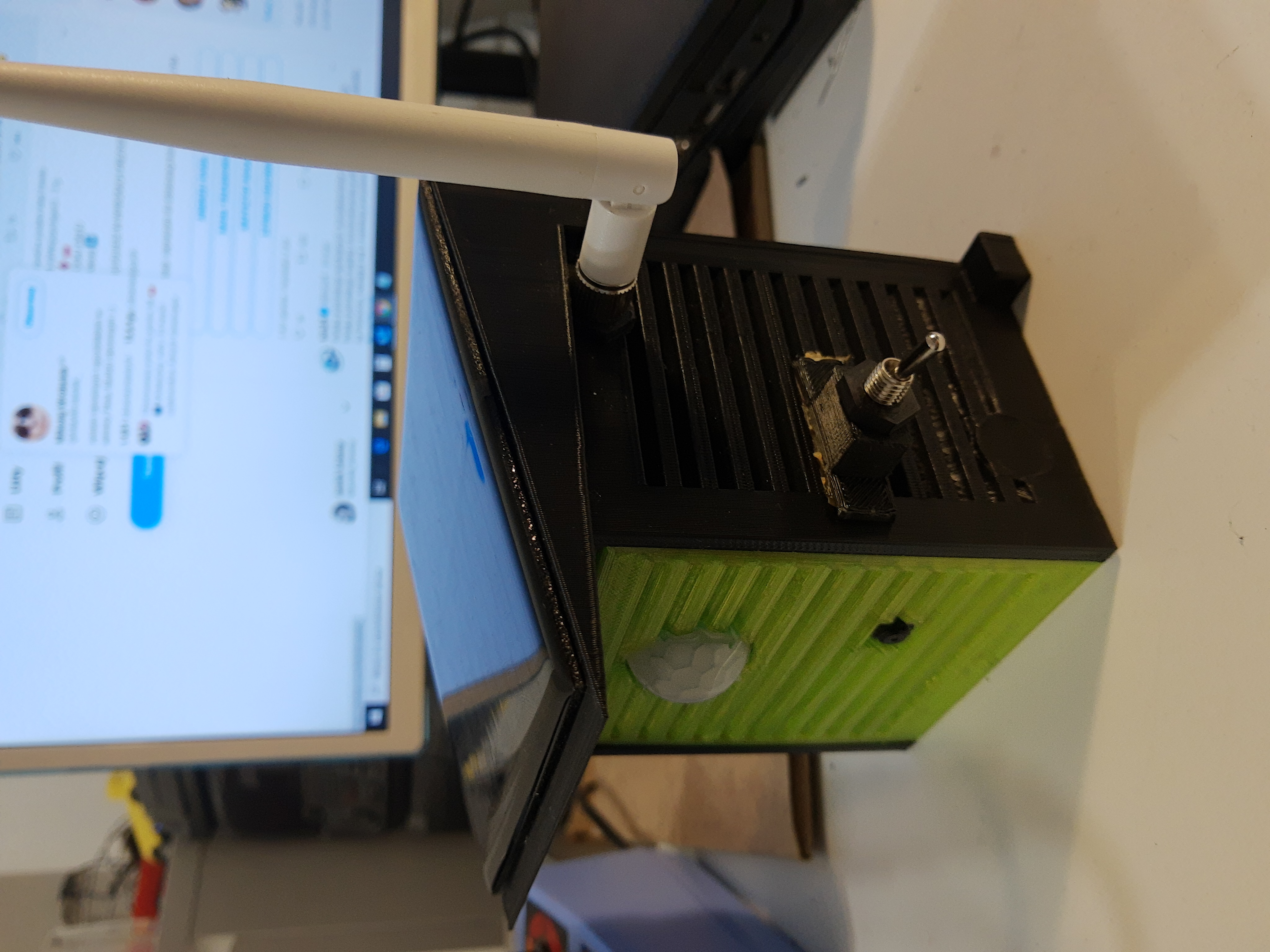
Coming soon - how to make enclosure


