Hi, I have some gates that are controlled by a FAAC 452 MPS (wiring info here.
I’ve put an ESP32 in the gate control box to verify that I can get wifi connectivity to it and also have added BME280 and BH1750 temperature / humidity / pressure and light sensors via the i2c circuit of the ESP32. This will allow me to check its reliability in the short term over wifi.
I want to be able to trigger the gate to open using the ESP32 using gpio’s.
Looking at the diagram I can see that I need to use pin 9 on the low voltage connector to open the gate. Looking at the existing control unit, there is a GPRS device linking 14 and 9 as a result of a successful phone call. I don’t use the GPRS device any longer.
So I think I need to close the circuit between 9 and 14 briefly (pulse) to trigger the opening. Is this possible connecting the ESP32 directly in some way, or will I need to add a relay in between for the ESP32 to control this?
Probably is possible to use GPIO pin directly to connect pin 9 to ground.
But if someone accidently ask me about - I will use relay or optocoulper. To be on safe side.
I’m not sure myself, but there is a vcc pin which I can connect to the 5v on the Esp32 and then connect the commanding gpio pin to the “in” pin. The notes states low level of 0-1.2 to trigger the module…
Oh you are using the relay BOARD not just the naked relay. Yer doing it in easy mode.
The naked relay consumes too much current to use it directly with a GPIO pin. You need both a cheap transistor and a Schottky diode to work the naked relay correctly.
Not sure if you were replying to me but I get them on Ebay or much cheaper on aliexpress in 5’s or 10’s. I tend to use them if I using mains power and transistors if using battery power.
I bought mine on AliExpress and, as it turns out, they did not come with a relay board at all. That is why I was asking about specific sellers. Thanks.
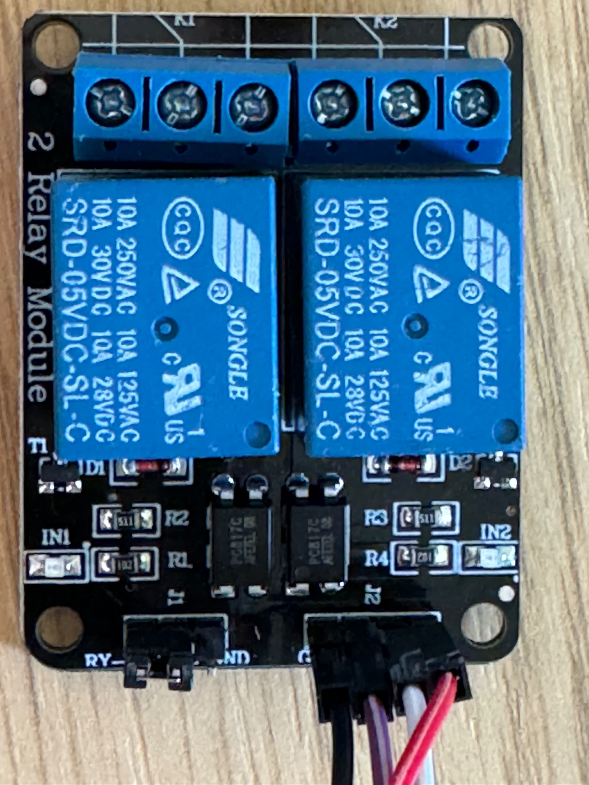
So I have my relay board here and I’ve wired it up to an ESP32 (along with BME280 for temp / humidity and BH1750 for Lux via I2C). I’ve also configured ESPHome with the config for the I2C devices and pins for the 2 relays on the board.
I’ve loaded this to the ESP32 and it’s all working well and the relays are ticking over which is great.
Only question I have is regarding the pin voltage from the ESP32 to the trigger pins on the relay. On the Temu site I think it recall it saying 0-1.6v, but the ESP32 is obviously outputting 3.3v on the pins. I can’t see the info on the Temu site anymore, so can’t check. I can see that the relays themselves are slightly different to those pictured on Temu. Is there a way I can tell from the Octocoupler or something if 3.3v is going to be ok on the signal pins?
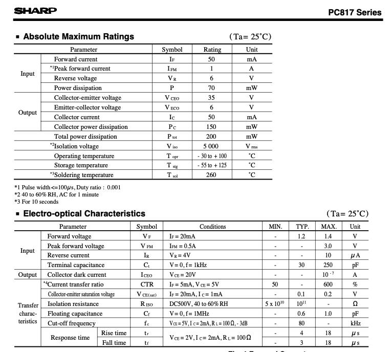
Not sure if I’ve found the answer myself as I’m no electronics engineer. I’ve found this specification for the PC817C optocoupler (different manufacturer).
I see the Max rating for Emitter - collector voltage is 6V, is this the rating that applies to the input pin driving the opto-coupler? If so, then I think I should be fine on the 3.3v?
It tells you right on top of the relay. It shows its AC/DC limits as well as current(Amp) limit and then under all that is possibly a model number, im not 100% sure but in there as well is a 5v. Thats specifies the operating voltage, 5v.
As far as 3.3v some 5v relay modules will work Ok at that level and some dont work so well and need 5v. It really depends on how you plan to use them though. If you’re going to pull the gpio High and use a logic Low trigger then usually(in my experience) they work fine on 3.3v. If you do a logic High to trigger the relays then you may have issues with it not being enough to open relay.
In all honesty. You should just try it and see what happens. Here, the worst case is you undervolt it and it wont work with 3.3v. Nothing is going to blow up or carch fire here so give it a go and try to troubleshoot it yourself at first, this is the best way to learn this stuff.
I could not get the SRD-05VDC to open with 3.3 volt signal. I needed an SRD-03VDC and I also needed to supply pin power to the base of a 2N2222 whose high current path triggered the transistor in turn. I was so pissed off at buying the 05VDCs because that added an extra two weeks.
Later I would come to find out that, if I had 5 volts handy (I did not — I had 24 volts and a step-down to 3.3v for the ESP), then I could have piped those 5 volts across collector and emitter of the transistor, and signaled the transistor using the GPIO pin.
Check out how I made it work (complete with diagrams and photos):
A for effort but, it might be better to focus on just learning and less teaching attempts. A lot of things you wrote were confusing or just dont make a lot of sense to me.
Im not sure why you chose a 24v - 3.3v converter and then shot yourself in the foot with your 5v relay. Most sensors/components are 5v tolerant or explicitly need 5v like in your case. There’s very little reason to be using or needing to power the esp with 3.3v. You are using a Dev board and it takes 5v In and runs in through an onboard regulator for the 3.3v needs. Doing it it that way with 5v power, it powers the board and gives you a 3.3v and 5v output to use for sensors or relays so you dont shoot yourself in the foot.
That simple change would have eliminated the extra and unnecessarily transistor and other components if people are using a relay module(which is the most common)
" * supply.
Make sure you buy LED strips that don’t require a PWM driver. Quite a few on the market will need that. Relays can’t do that. Generally, if a strip is specified to require a driver instead of a simple power supply, that strip can’t be used here. An explainer on constant current vs. constant voltage can be read here."
This makes no sense to me. You’re already telling people to use transistors for their relays and a “PWM Driver” is just 1 orna group of transistors/mosfets and wiring them would be almost identical.
There couod be someone else out there who would want 12/24v binary led’s but, again thats not going to be most people. Instead of telling people to completey avoid led’s that require a controller, instead explain Why and the differences because, CC and CV arent the only 2 options for choosing led’s.
The esp32 or esp8266 can and should 100% be used as the “led controller” and it’s extremely common practice to do so. Recommending led’s that can be controlled with their esp32 and offer dimming at the very least and possibly RGB+W for those people who didnt go to school with Thomas Edison and like those lighting features.
Maybe im missing your point and you can explain why you say to avoid led’s that require a controller?
"
Do not power an LED strip that is rolled up for more than a few seconds. It will overheat. It must be unrolled first."
Led’s for the most part and especially led strips, they dont generate much heat at all. They definitely dont generate so much heat that there is some high risk by having them rolled up. There are some interference issues that can come from certain rolled up strips but heat? No. No heat.
Dont take it the wrong way, I definitely appreciate your hard work and putting it into this guide. I just think it adds unnecessary confusion and not so great recommendations and instructions to people already very confused.