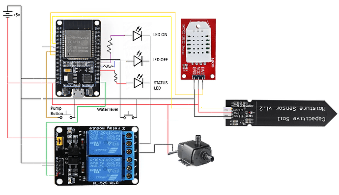
Hi everyone, I’ve been playing with ESP32s for a short while, but I’ve learned in a short time.
I’m designing a small irrigation system for my plants, before assembling it I’m trying everything on a BreadBoard, and everything seems to be going well, except when I turn on the pump, in that case the ESP32 goes crazy randomly turning the relay and LEDs on and off, and I find the message in the log: “[dht:174]: Requesting data from DHT failed!”
The whole system is powered by 5v with a MeanWell DR-15-5 power supply, the voltages are stable and perfect.
If I try with a motor like this → Mabuchi Motor RF-300 then the problem doesn’t occur, even with 3 of these turned on at the same time.
I can’t understand why it happens and how to solve it.
This is my esphome yaml:
esphome:
  name: "irrigatore"
  friendly_name: Irrigatore
  area: Home

  on_boot:
    priority: 800
    then:
      - switch.turn_off: Pompa

  on_shutdown:
    then:
      - switch.turn_off: Pompa

esp32:
  board: esp32dev
  framework:
    type: esp-idf

# Enable logging
logger:

# Enable Home Assistant API
api:
  encryption:
    key: "NB+M8OzBcEpB0MA2Tl7jhNjD/qzlPlc77z5nkjjCH2k="

ota:
  - platform: esphome
    password: "c06bf487b779e1626a91b3d5a5b279df"

wifi:
  ssid: !secret wifi_ssid
  password: !secret wifi_password
  enable_btm: true
  enable_rrm: true

  # Enable fallback hotspot (captive portal) in case wifi connection fails
  ap:
    ssid: "Irrigatore - Fallback Hotspot"
    password: "Qhckalnovka3"

captive_portal:

time:
  - platform: sntp
    id: my_time
    timezone: Europe/Rome

binary_sensor:
  - platform: status
    name: "Irrigazione - Stato Rete"

#Pump button
  - platform: gpio
    pin:
      number: GPIO33
      inverted: true
      mode:
        input: true
        pullup: true
    name: "Pulsante Pompa manuale"
    on_press:
      then:
        - switch.toggle: Pompa
        - light.toggle: led_on
        - light.toggle: led_off
        - logger.log: Pompa in modalita' manuale

  - platform: gpio
    pin:
      number: GPIO17
      inverted: false
      mode:
        input: true
        pullup: true
    name: "Recipiente acqua"
    on_press:
      then:
        - light.turn_on: led_on
        - light.turn_on: led_off
        - logger.log: Bidone dell'acqua vuoto

status_led:
  pin: GPIO2

#Pump Relay
switch:
  - platform: gpio
    name: "Pompa"
    pin:
      number: GPIO32
    inverted: true
    icon: "mdi:sprinkler"
    id: Pompa
    restore_mode: always_off

#Pump LED
output:
  - id: ledon
    platform: gpio
    pin: GPIO16

  - id: ledoff
    platform: gpio
    pin: GPIO4

light:
  - platform: binary
    id: led_on
    name: "LED Pompa ON"
    output: ledon
    icon: "mdi:led-on"
    restore_mode: always_off

  - platform: binary
    id: led_off
    name: "LED Pompa OFF"
    output: ledoff
    icon: "mdi:led-off"
    restore_mode: always_on

sensor:
  - platform: wifi_signal
    name: "Irrigazione WiFi Signal"
    update_interval: 30s
    id: wifi_signal_db

  - platform: copy
    source_id: wifi_signal_db
    name: "WiFi Signal Percent"
    filters:
      - lambda: return min(max(2 * (x + 100.0), 0.0), 100.0);
    unit_of_measurement: "%"
    entity_category: "diagnostic"
    device_class: ""

  - platform: uptime
    name: "Irrigazione Uptime"
    id: uptime_sensor
    update_interval: 60s

  - platform: internal_temperature
    name: "Temperatura del sistema"
    icon: "mdi:thermometer"

#External temp sensor
  - platform: dht
    pin: GPIO25
    temperature:
      name: "Irrigazione Temperature"
      icon: "mdi:thermometer"
    humidity:
      name: "Irrigazione Humidity"
      icon: "mdi:water-percent"
    update_interval: 30s

#Soil humidity sensor
  - platform: adc
    pin: GPIO35
    name: "Soil Humidity Sensor"
    id: soil_humidity
    accuracy_decimals: 0
    update_interval: 5s
    icon: "mdi:flower"
    device_class: "moisture"
    unit_of_measurement: "%"
    attenuation: 12db
    filters:
      - calibrate_linear:
          - 2.25 -> 0
          - 0.97 -> 100
      - lambda: |
          if (x < 0) return 0;
              else if (x > 100) return 100;
                  else return (x);
text_sensor:
  - platform: version
    name: "Irrigatore version"

  - platform: wifi_info
    ip_address:
      name: "Irrigatore IP"
      update_interval: 60s
    bssid:
      name: "Irrigatore BSSID"
      update_interval: 60s
    ssid:
      name: "Irrigatore SSID"
      update_interval: 60s

button:
  - platform: factory_reset
    name: "Restart with Factory Default Settings"

  - platform: restart
    name: "Irrigatore Riavvia"

  - platform: shutdown
    name: "Irrigatore Spegni"
    icon: "mdi:power"

  - platform: safe_mode
    name: "Irrigatore Safe Mode"


