I asked Waveshare too and here is their response :
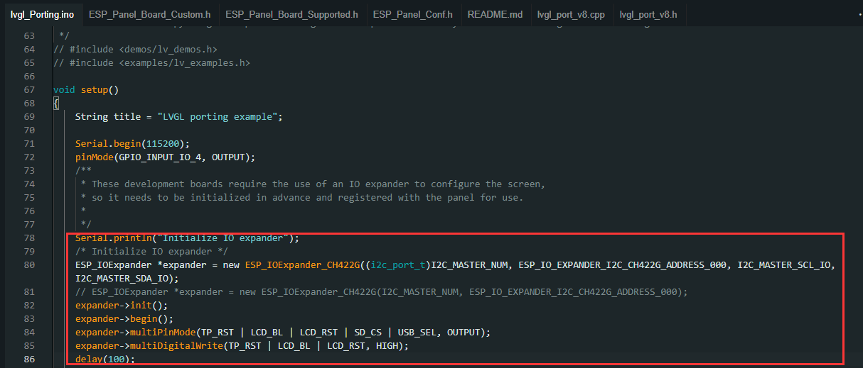
####################################
Hello
This is to initialize CH422G
expander->multiDigitalWrite(LCD BL, LOW);
When you need to turn it off, just add this command
After executing, you can turn off the backlight:
Do you have a photo or something that shows where the wire actually goes on both ends? I’m getting one of these next week, and I definitely want to be able to dim the screen. I see where to solder one end based on your picture, but I can’t for the life of me figure out where the other end goes based on the board diagrams on the Waveshare site.
OK, I took another look at the original post, and now I think I know how this will work. GPIO6 is used for the sensor interface. If you look at the description, that is pinned out into a 2 pin connector on the top right on the board (if you’re looking at it from the back). One pin is “data” and the other is power. For the dimming, you won’t need power, you just need to get a signal over the data pin. So I think if you solder the black wire from a 2 pin connector to that little pad and then plug it into the sensor port, then you can define A PWM connection in ESPHOME using this:
From there you define a light which you can dim or turn on/off.
My Waveshare display came yesterday, and I got the backlight dimming working. I forgot to take a picture before I put in the case I printed, but I think I can explain without it. I took one of the 2 pin cables that came with the display, bent the black pin just a bit so it would touch the pad noted in the OP’s picture and then soldered the pin to the pad. I then plugged the other end of the cable into the RS485 jack on the back of the display. You aren’t actually doing RS485, but this is how you get access to a GPIO pin. Plugged in this way, the GPIO you’ve just attached to is GPIO16. I ended up using that one because I didn’t see any world where I’d ever use the RS485 interface, and I still have the IC2 and sensor interfaces to use later if I want to. I then use this YAML to control things:
The output defines the control for the backlight. The light defines the dimmer that will get exposed in Home Assistant. There are two switch elements. One is anti burn (I got that from the ESPHome LVGL tips and tricks) that can be activated to have the display run a random pattern to prevent burn in (no, I don’t know if it’s actually an issue for this display). The other is an internal switch for the display backlight that MUST be present for the backlight to work at all. Since I can fully control the backlight from the light, I didn’t expose the switch to Home Assistant.
With this I can now write all the automations I want in Home Assistant. One will dim the screen as it gets darker in a room, one will turn the backlight off if there’s nobody in the room, and one will run the anti burn every hour but only if the backlight is off (i.e. nobody is in the room). Hourly is overkill, but I figure that’ll ensure it gets done at least a couple times a day.
As an aside, I tried to use this as a bluetooth proxy too. It would work for a while, but eventually the display would hang. I think trying to do Bluetooth and WiFi at the same time plus controlling the display was just too much. I might try tweaking the bluetooth proxy settings later, but for now I may just dedicate some existing ESP32’s I have to bluetooth proxy.
I have a Waveshare screen of the type discussed in this thread, so I’m finding this useful. I’d like to summarize what I’ve read to make sure I’m understanding this correctly. Please let me know if what I’m saying is right or wrong.
It looks like there are three ways to handle the backlight:
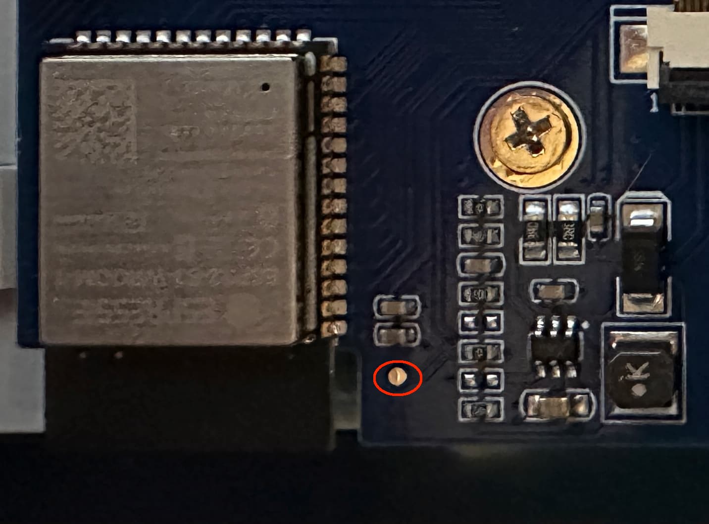
Solder a wire from the pad on the PCB to a pin on the ESP32. I’ve circled the pad in red and the suggestion in the post was to solder the wire to GPIO6. However, I don’t see verification that anyone has actually done this and verified it works with GPIO6. (And I’m not clear on configuration. I would think it would mean to set up GPIO6 as an LED so it would be driven by PWM. I see PWM mentioned, but I’m not clear about the setup.)
It can be turned on and off, but cannot be dimmed by using the CH422G, which involves configuration work. That includes using the console to activate the CH422G, then setting it up in the configuration in the YAML file. This seems to be the easiest way to set it up, since it does not involve any soldering or hardware changes. (I haven’t done a lot of soldering for years. From my point of view, making hardware changes, unless one is 100% sure of what they’re doing, always involves more risk than software solutions because a slip or a drop of solder or just a bad solder can ruin the board.)
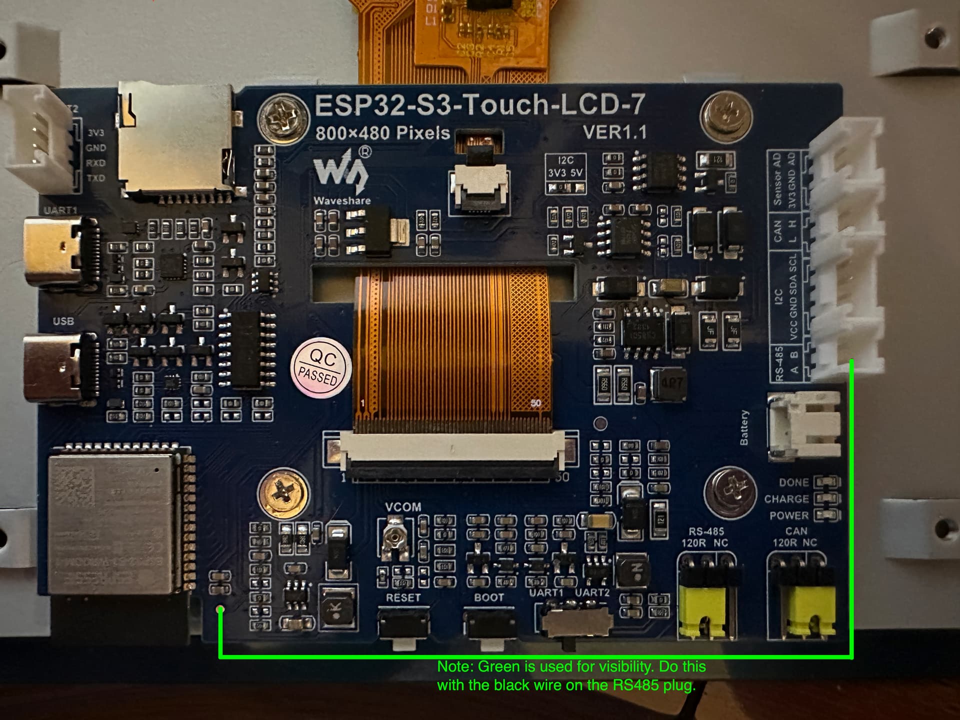
I want to clarify this, with your help, @pkscout. In your first post on using the RS485 connector, you reference GPIO6, but in your next post about it, you say the black wire on the RS485 connector is connected to GPIO16. It’s GPIO16, correct? I’ve marked up a picture of the PCB to show what I am pretty sure you did for the wiring. Could you please verify? (I used bright green instead of black for the wire for visibility.)
A few points I’d still like to ask about with this method:
I) You still have the CH422G referenced in the configuration. Is this still needed, since the RS485 black wire connects directly to GPIO16? Or is it that you’re using Method 2 (as I counted them) to turn it on and off, and the wire you added for dimming? If this is so, how dark can the backlight be if it’s just adjusted through PWM and not turned on and off through the CH422G?
II) You talk about “anti burn.” I have seen the section in the Tips and Tricks that I think you’re referring to. However, I was under the impression that the snow needed to be left up for a good while to avoid burn in. (For instance, whenever the screen was not in use, dim or turn off the backlight and put snow up.) Will just putting it up for a short bit periodically be enough to prevent burn in?
It’s actually easier than that. I didn’t have to enable anything on the console. I just added the config for the CH422G and it just works. The display backlight can be turned on and off. Easy peasy.
There technically isn’t a “correct” GPIO. You can use whichever one you want. I decided I wanted the potential to easily use IC2 devices later, and GPIO6 would have conflicted with that. GPIO16 was on a 2pin connector, so it was the smallest connector and on something I knew I’d never use. You just have to match the YAML config in the output section to whatever GPIO you use.
Yes, the CH422G part of the config is required. If you don’t include it, the backlight will never turn on. But the PWM interface can control everything (dim and on/off), so you don’t really need to use the CH422G switch.
I honestly have no idea. I suspect that the burn in will only be a problem after years of usage, and what I’m doing is running anti burn for 30 seconds about 12 or so times a day. It might not help, but it won’t hurt.
I’ve made the hardware mod, and left the CH422 stuff as original. Where do I put the GPIO16 ? In place of the CH422? or added?
If someone could upload a working config with the RS485 → Via (red circled) I would be grateful (have 2 bd’s modded, but blank screen.)
Thanks!!
So you are using the CH422G to turn it on and off, but also using the connection through the RS485 for dimming? If I didn’t use the CH422G, then I’d only be able to dim it, but the backlight would never be fully off? (Okay - what you wrote below about using the PWM interface finally “clicked” in my head!)
I’m wondering if I’m misunderstanding something. I set my system up without even referencing the CH422G and it’s working without issue - nice and bright display.
I missed this my first 2 read-throughs, but just read it again, as I’m writing this reply and it finally registered in my head. So if my device is working without the CH422G part of the configuration, the one thing I need to do if I want to control the backlight is run that wire. Just double checking that the wire I drew in green in my pic is basically what I need to do?
You set CH422G’s IO2 as a switch with default state to ON to turn ON the backlight. Same as “stock config”.
Then with GPIO16 from ESP32-S3, you create a LEDC output component, wire from RS-485’s “A” pin to the testpoint labeled above.
With correct ESPHome config. You just leave CH422G IO2 always ON and just use your monochromatic light entity to control LCD Backlight brightness.
The backlight control of CH422G IO2 now just becomes a static output always set to ON. The actual setting of backlight On/Off and brightness is now completely handled through the monochromatic light entity mapped to GPIO16.
I have a working version now. More details on it later, after I’ve had time to test it. I just want to make one correction for those working on getting their screen to work.
I thought the CH422G was not even mentioned in the config file I was using. I have to correct that: It was. It wasn’t given an ID or name or anything else, but it was in the config file.
Also in that config file was a switch for just turning the backlight on and off. I realize, now, that this config file I was using is intended for a different 7" LCD screen from Waveshare. I had not worried about the backlight switch in that one, since it was using another GPIO pin and was doing nothing.
In my current config, the web page has a control for the backlight that includes a 0-255 slider and an on/off switch that, apparently, does not go through the CH422G to turn it on and off. (I think it just changes the level to 0.)
I’m finding a few glitches between the file I was using (that I found was meant for another Waveshare device) and the settings for this particular device, so I’m still working those out. When I do, I’ll post pics and describe what I did and what I used on this thread to make it work.
This post above you in this thread has a working config (well config snippet anyway):
You need to scroll down to see the whole thing. But just for completeness, here’s a link to my entire YAML file for this display. It includes everything I setup to use it as a weather clock, so you obviously don’t need all of that. But it might be helpful to have a complete, working config in one place.
It’s available within Home Assistant. That allows me to have a tile where I can manually dim/brighten the clock as well as have some automations that change the dimming level of the clock based on the light level in the room (and turn the display off is nobody is in the room).
It’s been a while, but everyone is as passionate as ever. Connecting GPIO6 to the sixth pin from the bottom on the right side of the ESP32 module makes it neat.